Here step step testing. 1 Unplug module connectors 2 a spare headlamp load test powers grounds. should a bright light you connect from brown wire (Connector 1 pin A1) the black wire (connector 2 pin A) when connect red wire (connector 2 pin B) black wire (connector 2 pin A).
 I'm for wiring diagram my 2004 Colorado ABS system. have front speed sensor fault, short open, says control module. had bearing/hub issues I replaced front speed sensors a result. Sadly did fix abs fault. I the wire pin-outs do logical .

 It be authors the wiring diagram using terms haphazardly. to "Overview the DSC Systems" chart provide bluebee this link (near bottom), year 2000 BMW E46 an ABS unit is DSC III by Teves model MK 20 EI.
 C5 Tech - C5 abs wiring diagram - Good afternoon; anyone me to a wiring diagram complete abs system my 2000 C5. want trace circuits fuses. Bob:willy:
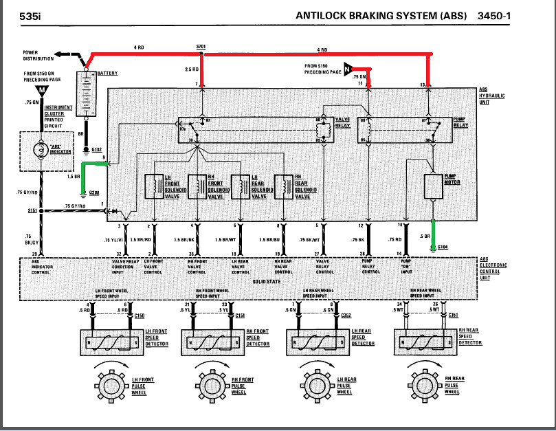 The document an ABS system wiring diagram shows connections the ABS control module, wheel speed sensors, brake warning lights, other brake components. ABS control module receives power the ignition switch relay sends receives bus signals components the instrument cluster powertrain control module. also controls pump motor .
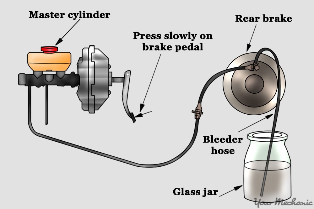
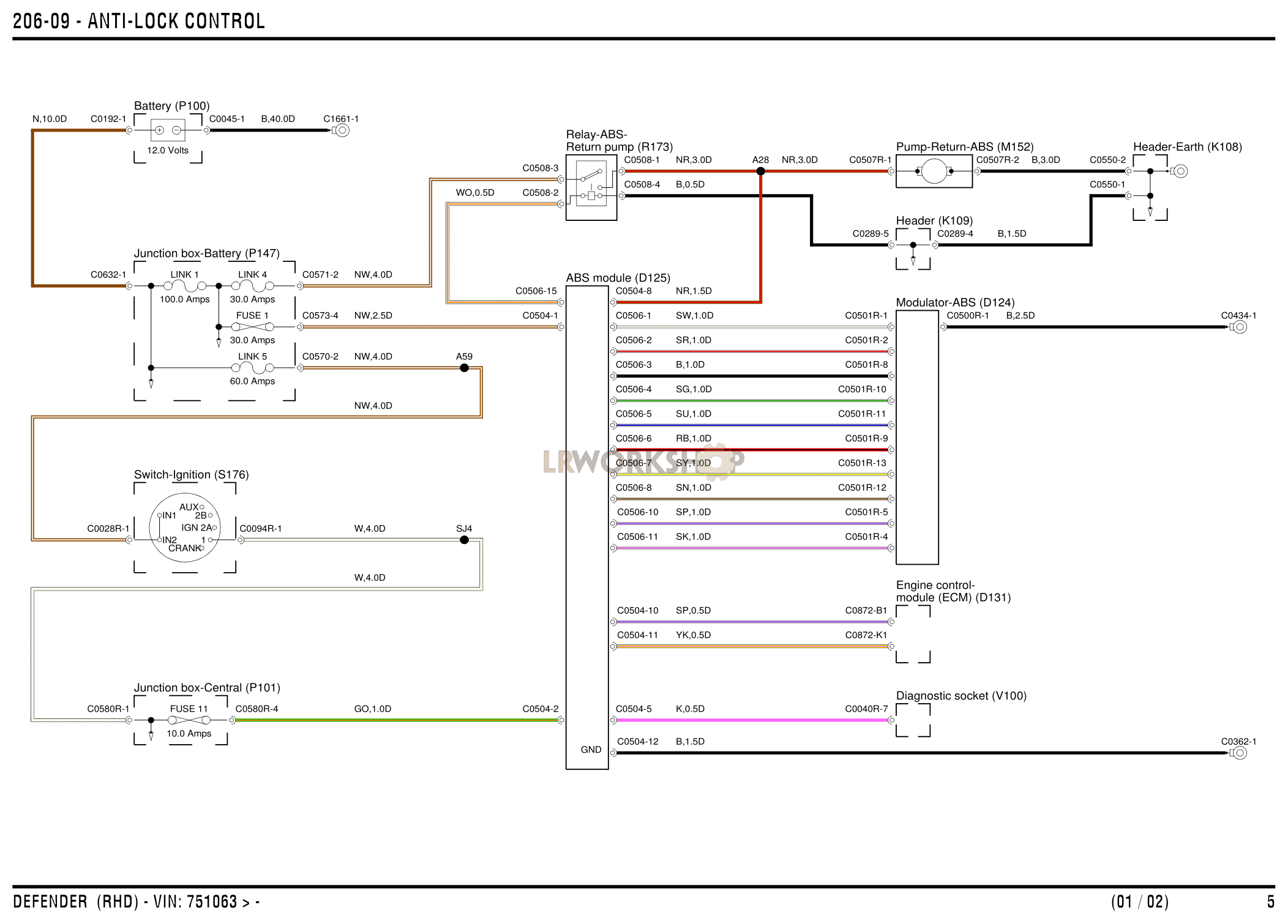 Would to check continuity ABS mass connector pins to origin. for pin diagram wiring color codes I check each wire the ABS connector up where goes underneath under-hood fuse panel/ECM. . 2000 Chev Silverado Abs Pump Unit Of Line Fitting Threads Stripped. Repair .
 Components Connections the ABS Module Diagram. 1. ABS Control Module: ABS Control Module a key component the ABS system a 2000 Chevy Silverado. is responsible monitoring wheel speed controlling pressure the brake lines prevent wheel lock-up braking. 2. Wheel Speed Sensors:
 ANTI-LOCK BRAKES Anti-lock Brake Wiring Diagrams, 310 ABS GMC Jimmy 2000List elements Anti-lock Brake Wiring Diagrams, 310 ABS GMC Jimmy 2000:(under left side dash) data link connector (dlc)4wd front drive ind lock in4wd ind sw inA10A12Abs fuse 22 10aAbs fuse 60aAnti-lock indicatorBody control module .
![[DIAGRAM] Meritor Abs Wiring Diagram Power Cord - MYDIAGRAMONLINE [DIAGRAM] Meritor Abs Wiring Diagram Power Cord - MYDIAGRAMONLINE](http://mainetreasurechest.com/wp-content/uploads/2018/08/wabco-abs-wiring-diagram-inspirational-wiring-diagram-for-wabco-abs-free-download-wiring-diagram-of-wabco-abs-wiring-diagram.jpg) [DIAGRAM] Meritor Abs Wiring Diagram Power Cord - MYDIAGRAMONLINE
[DIAGRAM] Meritor Abs Wiring Diagram Power Cord - MYDIAGRAMONLINE
 Abs Wiring Diagram Pdf
 Wabco Abs Wiring Diagram Plug
 Abs Plug Wiring Diagram
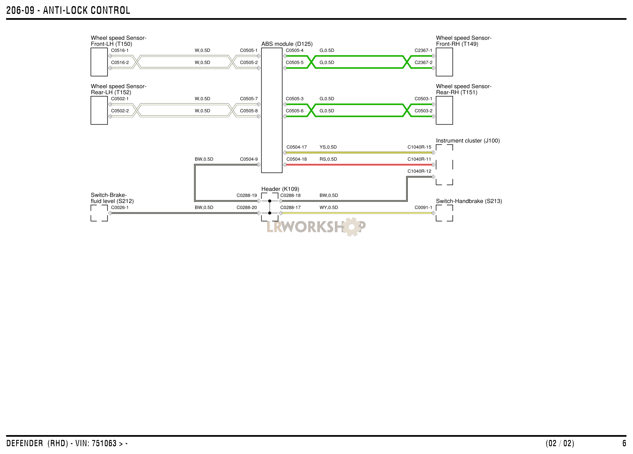 Anti-lock Braking System (ABS) Wiring Diagrams - Find Land Rover parts
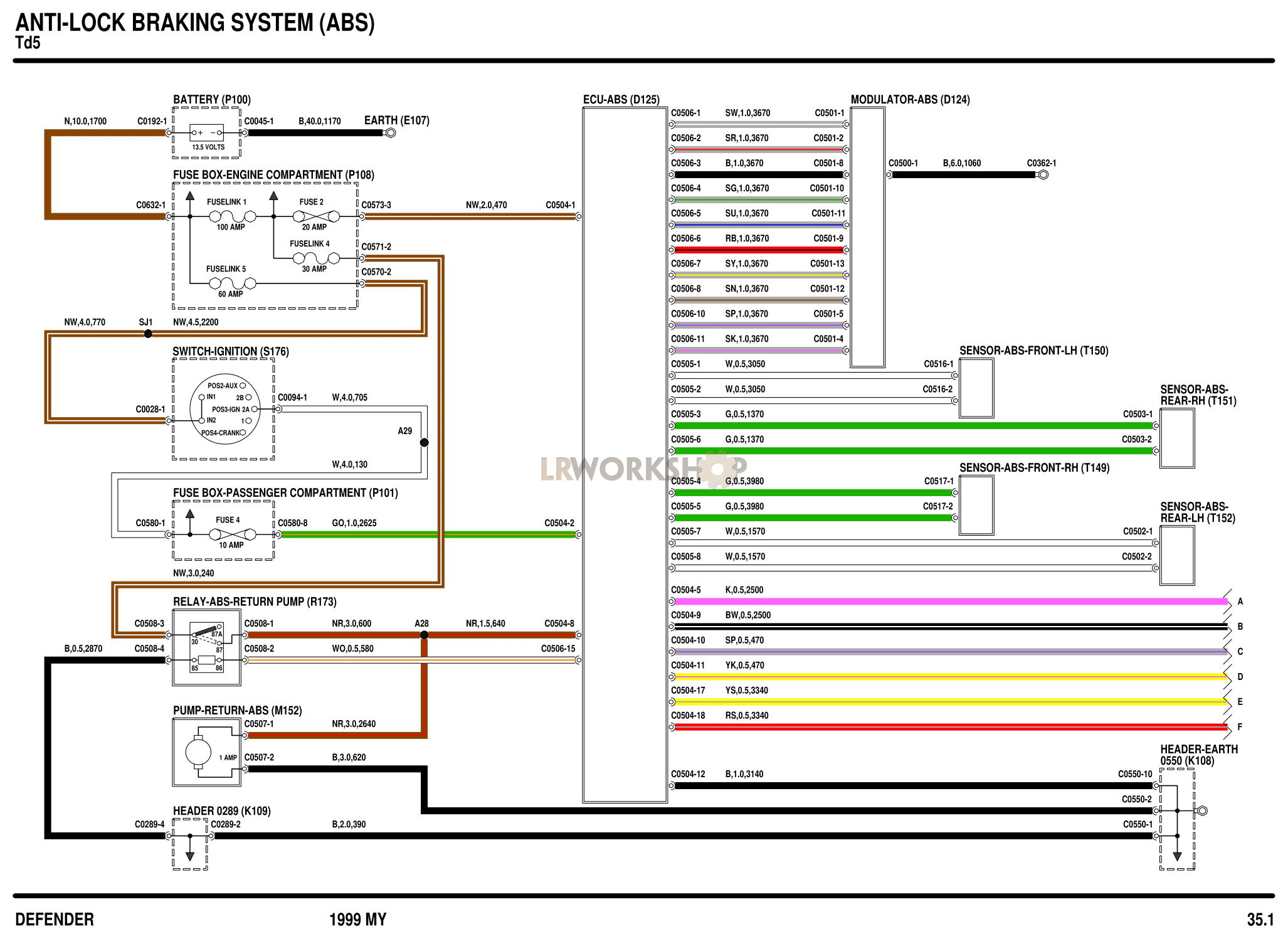 Haldex Abs Wiring Diagram
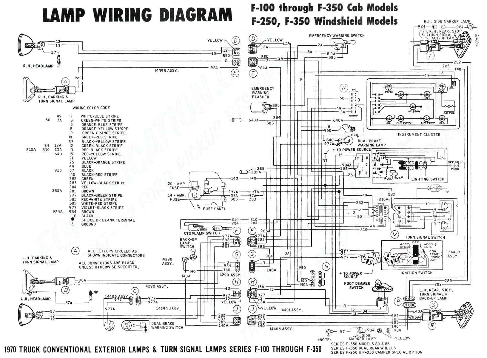 Abs Plug Wiring Diagram | autocardesign
![[DIAGRAM] Kenworth Abs Wiring Diagrams - MYDIAGRAMONLINE [DIAGRAM] Kenworth Abs Wiring Diagrams - MYDIAGRAMONLINE](https://i1.wp.com/autogeriko.com/files/1max_qk88lb7e.png) [DIAGRAM] Kenworth Abs Wiring Diagrams - MYDIAGRAMONLINE
[DIAGRAM] Kenworth Abs Wiring Diagrams - MYDIAGRAMONLINE
 ABS Module Wiring?: the Protective Tubing on My ABS Module Wiring
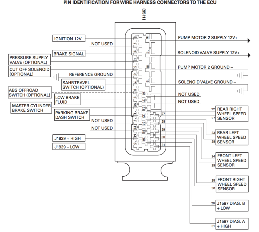 wabco abs wiring diagram - ShelliFenja
 wabco trailer abs wiring diagram - SajidahAliah
