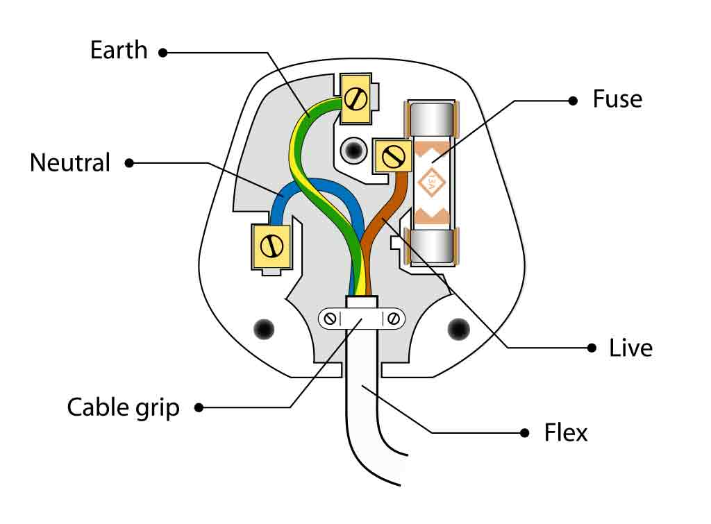
Using wire strippers, strip 1/2-inch insulation the of wire. Twist exposed copper strands each wire prevent fraying you attach to plug. Attach Wires the Plug. Open replacement plug access terminal screws inside. Attach exposed copper wire the terminal screw:
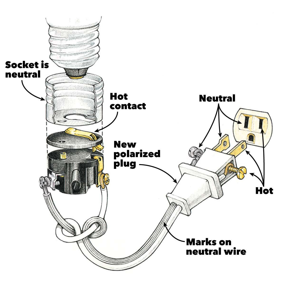 This page wiring diagrams for household receptacle outlets will encounter including: grounded ungrounded duplex outlets, ground fault circuit interrupters (GFCI), 20amp, 30amp, 50amp receptacles 120 volt 240 volt circuits. . slots different sizes accept polarized plugs it lacks grounding slot .
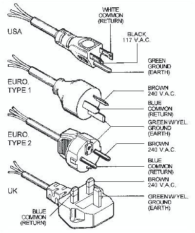
 The live/hot be connected the black wire, neutral the white, the ground wire the green. Type plugs neutral pin been slightly wider the live/hot wire. Type B plugs feature middle pin is to ground system. using middle pin ensures the plugs only put the correct .
 This ensures the plug the box now grounded. Next, attach white wire one the silver screws the left side the plug. lastly, black wire on right side the plug. (the brass screws). easy to remember wire where Black wire Brass screw. Black Brass start the letter "B .
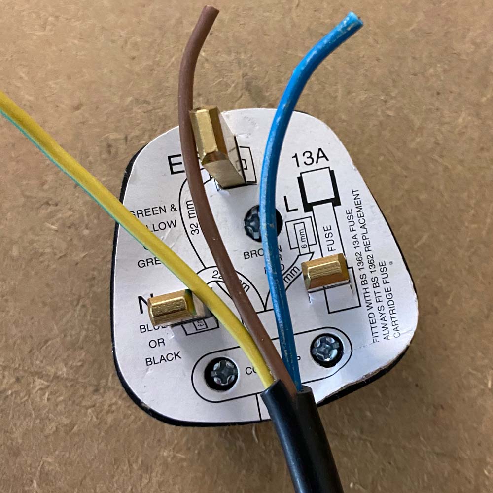
 Step 1: first step rewiring plug to cut the outer sheath (black) the flexible cable, get access the coloured wires underneath; give plenty wire work with. Line up the diagram the plug you see lengths cut. are coloured wires the cable; cable colours blue neutral, brown live yellow earth .
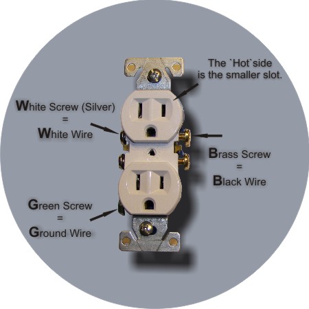 Wire plug maintain correct polarity. Wiring new plug isn't difficult, it's important get hot neutral wires connected the proper prongs. danger isn't fire. worry that miswired plug poses fairly shock hazard. key to sure connect wires the proper terminals the plug.
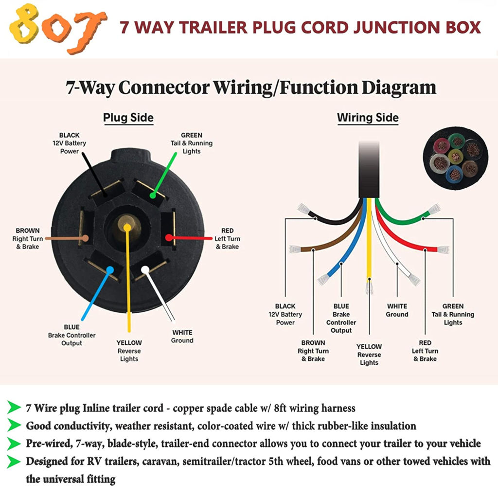 A 120 volt plug wiring diagram typically consists a diagrammatic representation the electrical connections the plug. shows configuration the wires, position the terminals, the color coding the wires. diagram serves a guideline wiring plug correctly, ensuring the live, neutral .
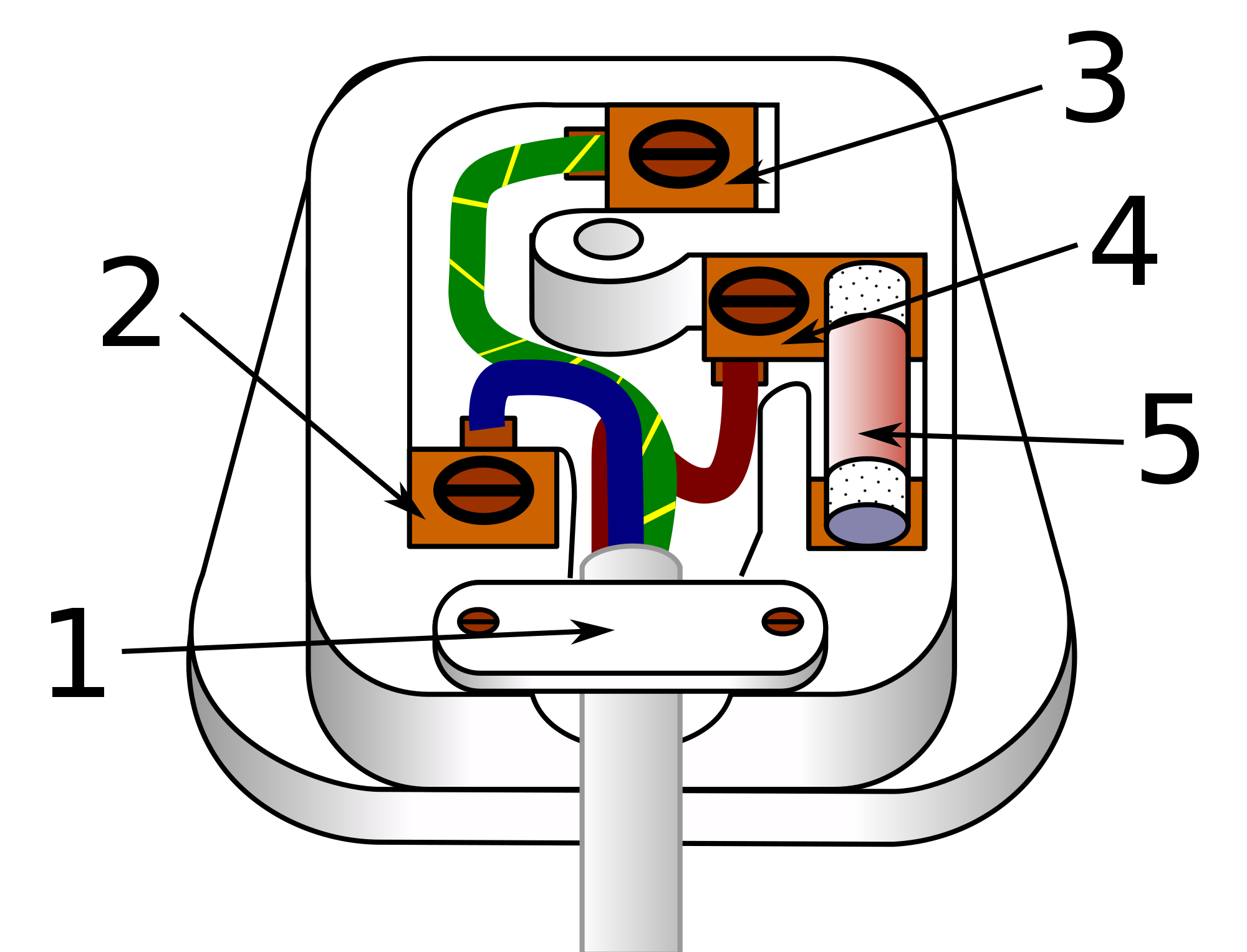 The wiring diagram a visual representation how various components the plug connected, allowing to easily follow correct wiring sequence. wiring diagram typically includes details as color-coding the wires, arrangement the pins, any additional markings symbols.
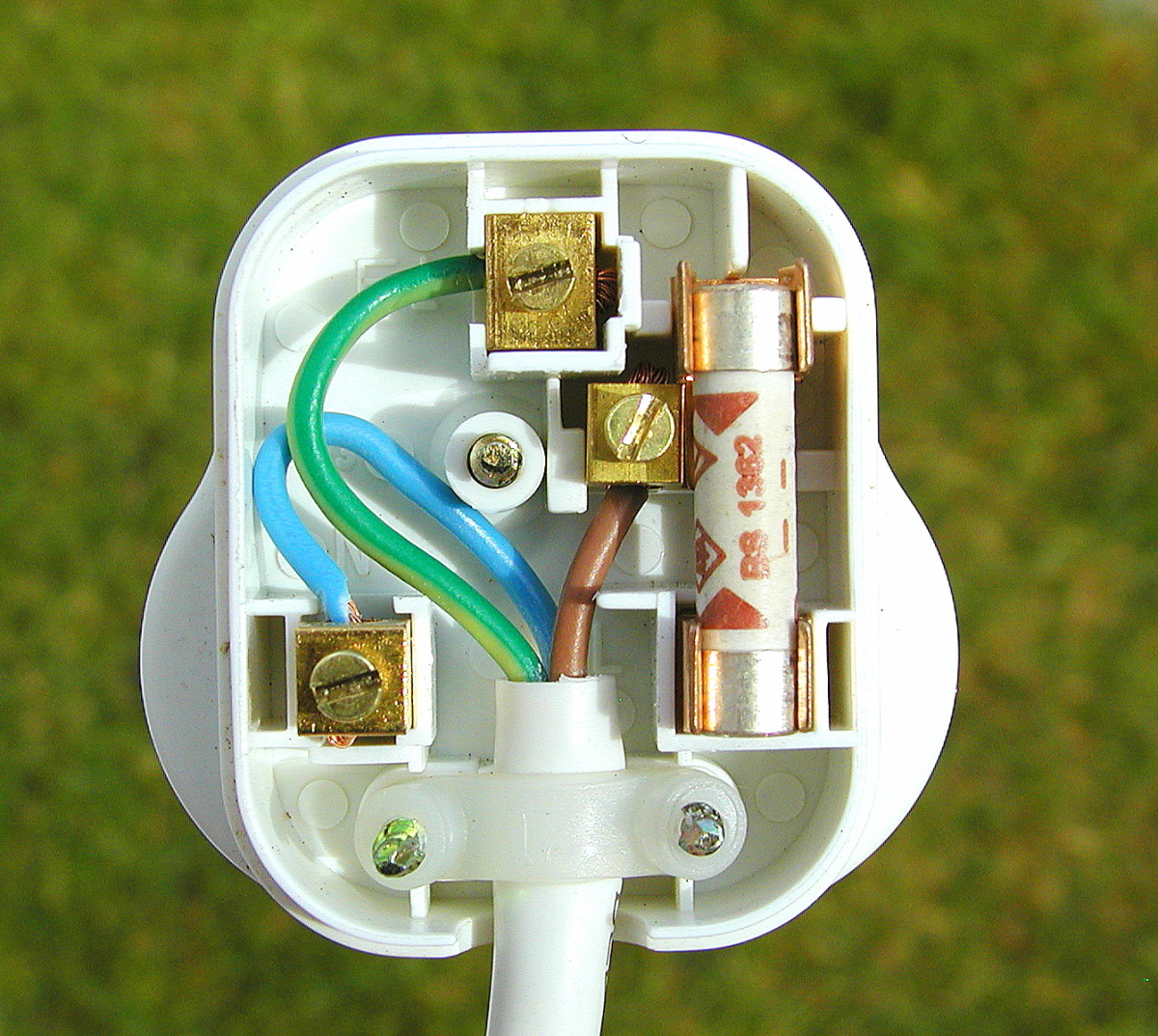 Understanding wiring diagram for electrical plugs essential ensure safe proper connection. diagram typically consists three main components: prongs, wire connections, the ground wire. component plays crucial role the proper functioning the plug the prevention electrical hazards.
 Wiring plug diagram a crucial aspect electrical work is essential skill homeowners, DIY enthusiasts, professionals alike. Understanding to correctly wire plug prevent electrical hazards ensure efficient functioning electrical appliances. diagram a visual representation the .
![[DIAGRAM] 7 Wire Plug Diagram - MYDIAGRAMONLINE [DIAGRAM] 7 Wire Plug Diagram - MYDIAGRAMONLINE](https://www.jkowners.com/forum/attachments/tool-crib/333386d1538372455-wiring-110-220-plugs-welder_final.jpg) [DIAGRAM] 7 Wire Plug Diagram - MYDIAGRAMONLINE
[DIAGRAM] 7 Wire Plug Diagram - MYDIAGRAMONLINE
 How To Wire A 3 Wire Plug
 50 Amp Plug Wiring Diagram - Artsist
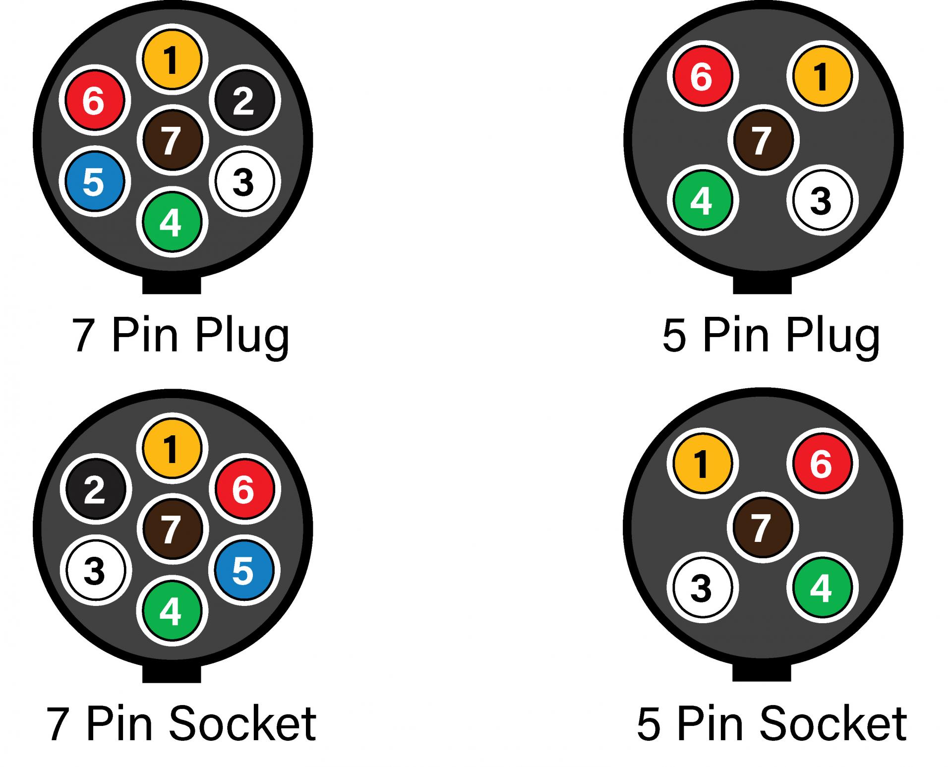 Wiring Diagram For A 5 Pin Trailer Plug - Schema Digital
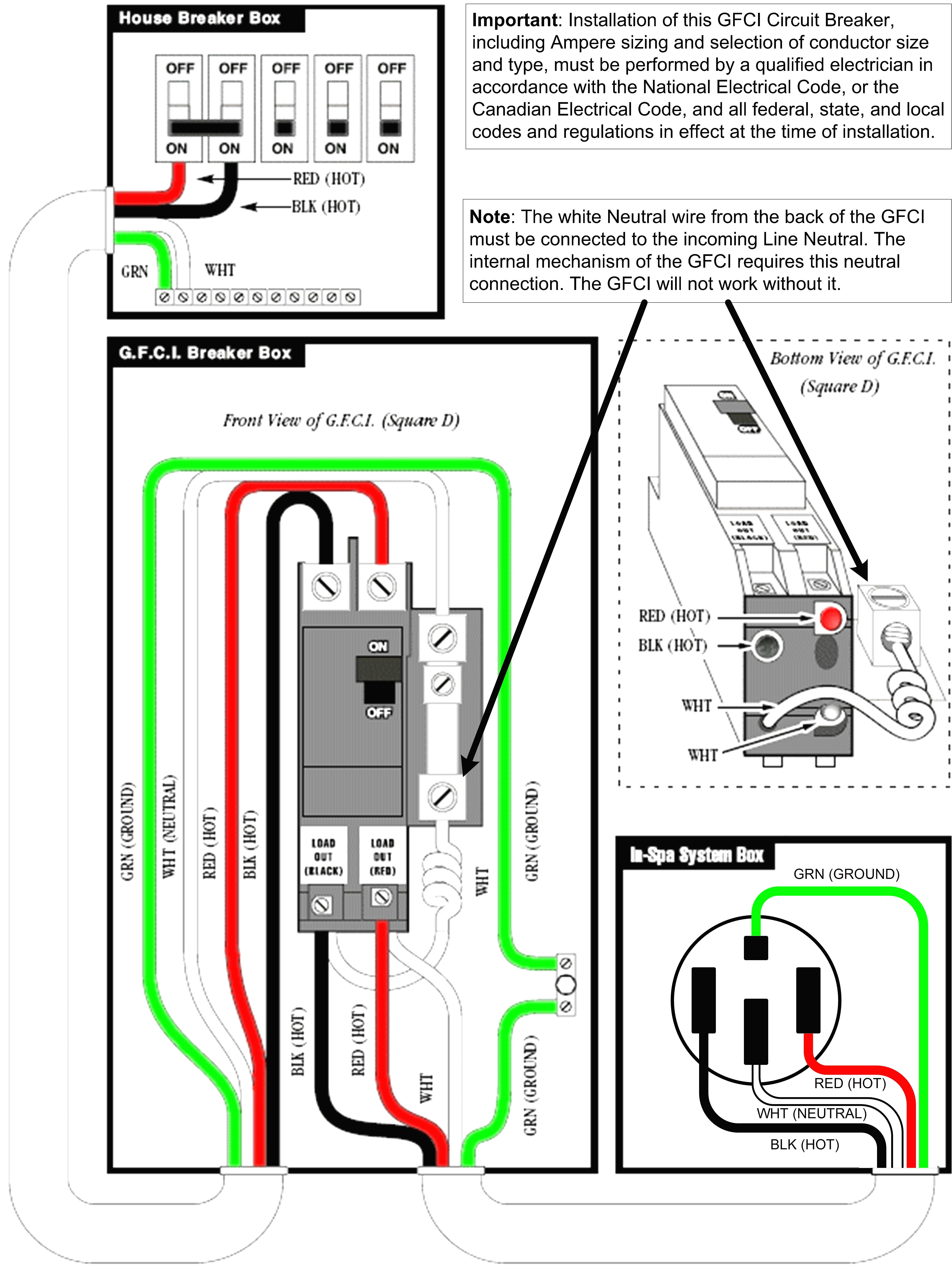
 3 Phase 5 Pin Plug Wiring Diagram Australia
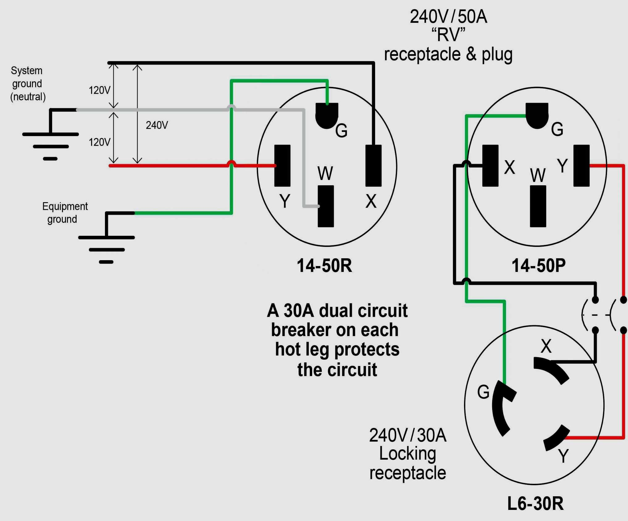
 240V Plug Wiring Diagram - Cadician's Blog
 How to wire a 7 Pin (12 N type) Trailer/Caravan Plug - How to wire a plug
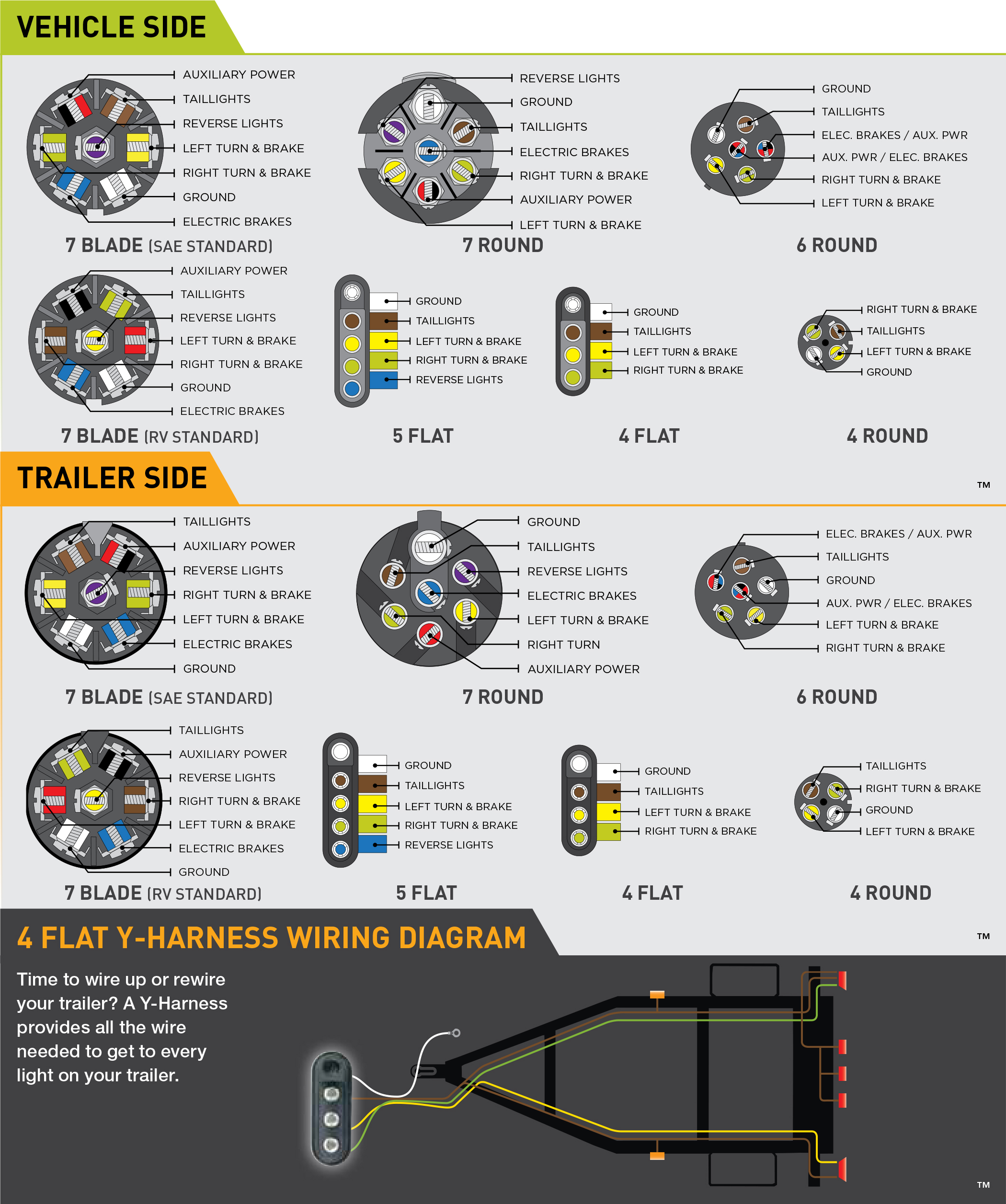 7 Way Rv Plug Wiring Diagram - Printable Form, Templates and Letter
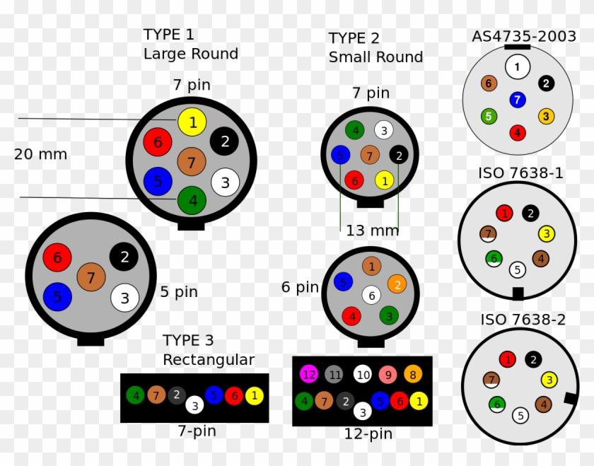 Three Phase 3 5 Pin Plug Wiring Diagram - Wiring Diagram and Schematic
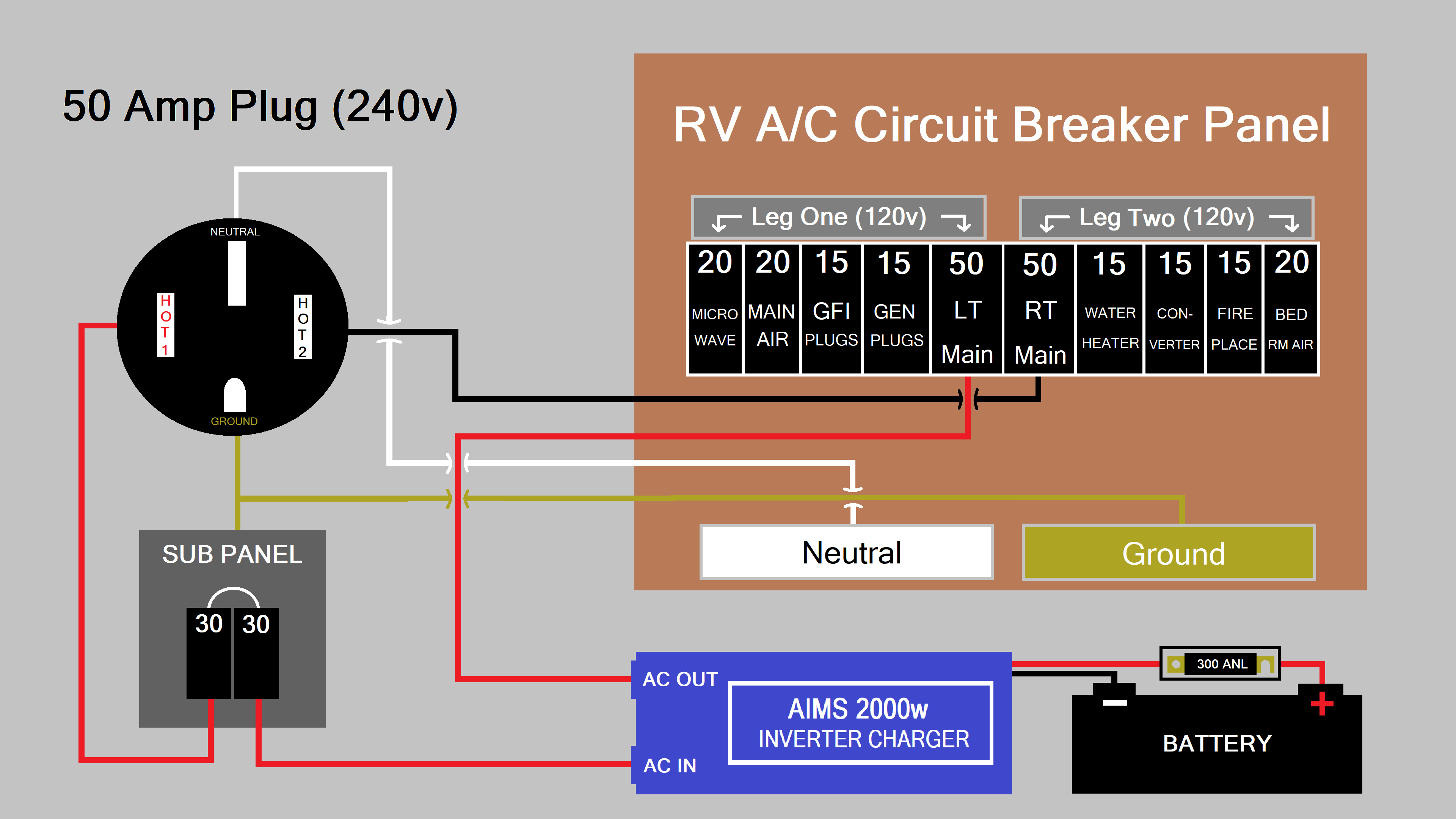 50 Amp Plug Wiring Diagram - Artsist
 Us Plug Wiring Diagram
