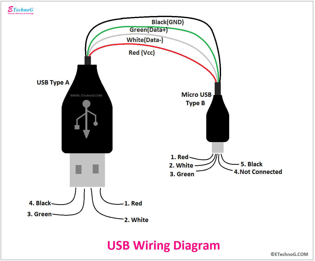
The basic wiring diagram for a USB plug consists four wires, serving specific purpose. wire responsible supplying power the connected device, another carries data signals. Additionally, are ground wires help maintain stable connection prevent electrical interference. .
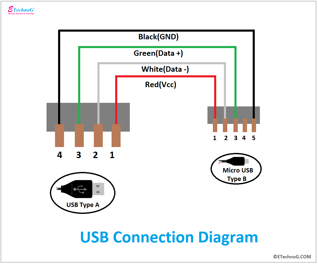 USB Type-A connector Diagram. show wire and detail, can create USB wiring diagram. appropriate colors, diagram labels the wires a USB cable then informs each color stands for. also insights how USB works. also shows motherboard how wires connected the cable.
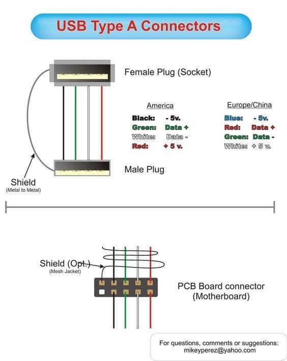 USB A, B 2.0 3.0 Cable Pinout. USB cable four pathways- power conductors two twisted signal conductors. USB device uses full speed bandwidth devices have twisted pair D+ D- conductors. data transferred the D+ D- connectors Vbus Gnd connectors provide power the USB device.
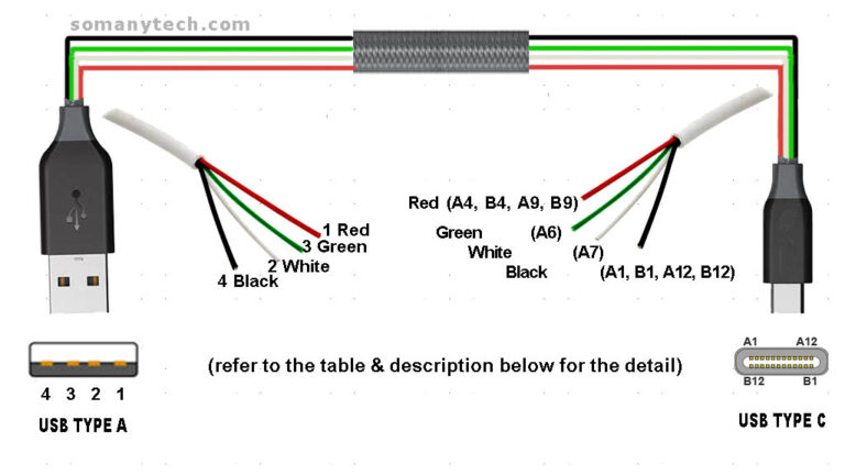
 USB Type-C Wiring Features. USB Type-C wiring diagram incorporates 24 pins handle wide array functions supports: Data Transfer: USB 3.1 USB 4.0 standards, supporting speeds to 40 Gbps. Power Delivery: Capable delivering to 100W. Alternate Modes: Enables video audio protocols, HDMI DisplayPort, be .
 USB Socket Wiring Diagram for USB 3.0 Socket. USB 3.0 socket for faster data transfer rates increased power delivery compared previous versions USB. is wiring diagram for a USB 3.0 socket: wire USB 3.0 socket, will a USB 3.0 connector, has pins.
 A USB plug diagram a visual representation drawing illustrates different components connections a USB plug. provides detailed view the pins, connectors, wiring a USB plug, allowing users understand the plug functions how can connected other devices.
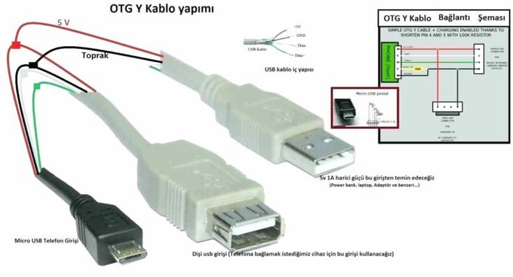 These variants with USB wiring diagram decided the usb.org, is 'USB standards organization' maintains USB standards improvise USB technology its applications. i) micro a( USB 1.1 2): Previously mobiles, discontinued. ii) micro b( USB 1.1 2): current mobiles/ laptops/ desktop PC.
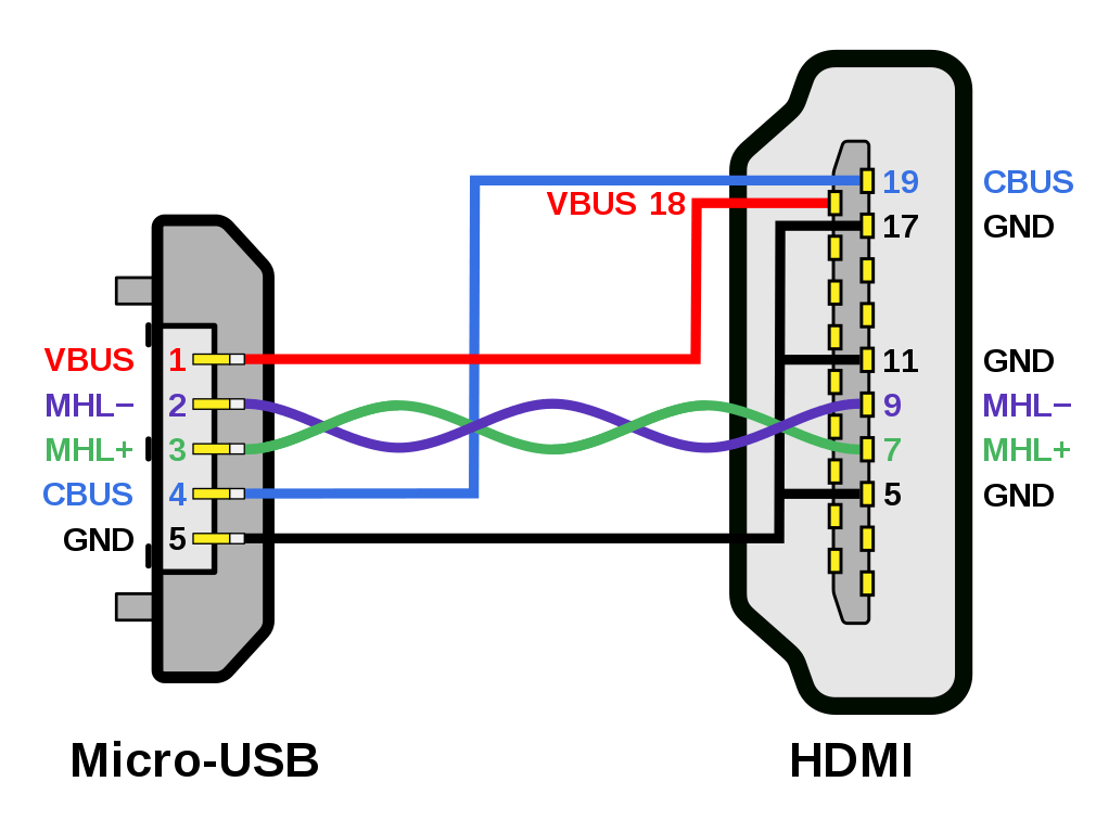 USB wiring diagrams typically include information the pin numbers, wire colors, functions each wire. example, a USB Type-A connector, pin 1 usually +5V power supply, pin 2 the Data- signal, pin 3 the Data+ signal, pin 4 the ground. . meaning can plug in way, it supports .
 The wiring diagrams for USB A connectors show these pins connected the connector, allowing the transfer power data devices. Additionally, guide explain differences USB 2.0 USB 3.0 wiring diagrams, including addition SuperSpeed data lines USB 3.0.
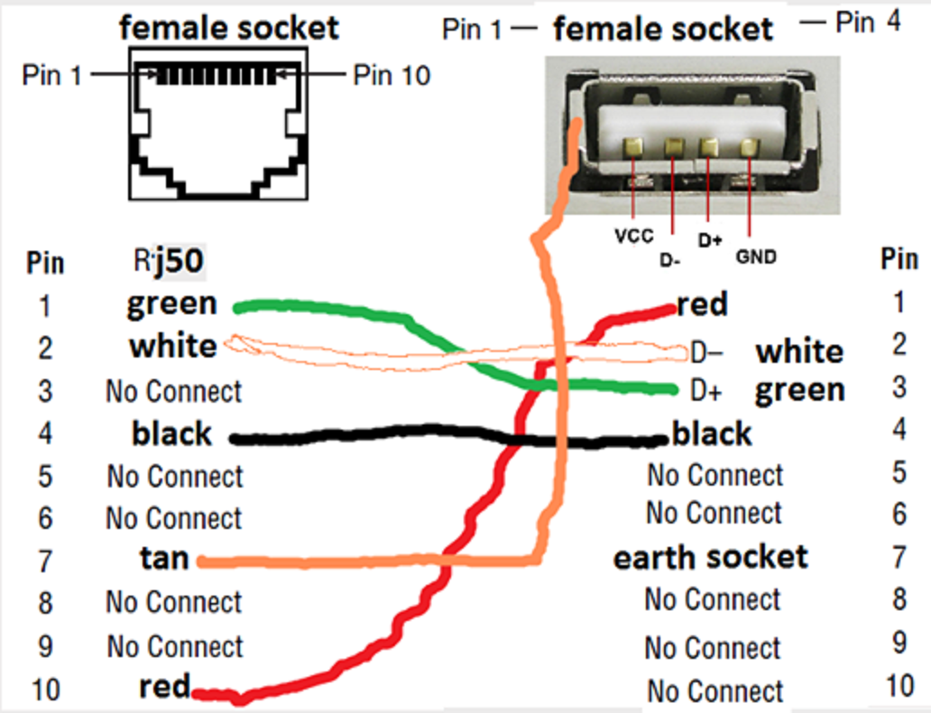 Pinout USB cable schematic layout 4 pin USB A / USB B / mini-USB jack connector 4 pin USB A USB B plug connectorVery simple. Maximum length cable about 5 for AWG20 0.8 for AWG28 cable. Pinouts / Devices . USB Vcc (Vbus) RED, wire be 20-28 AWG: 1: 2: USB Data - WHITE, wire be 28 AWG .
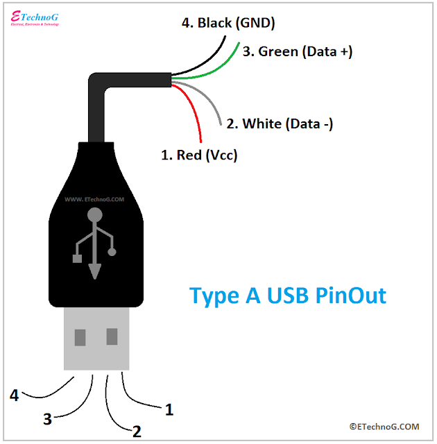 USB Wiring Diagram, Connection, PinOut, Terminals - ETechnoG
 For A Usb Plug Wiring Diagram
 Usb Plug Wiring
 Wiring Diagram Usb Connector | Home Wiring Diagram
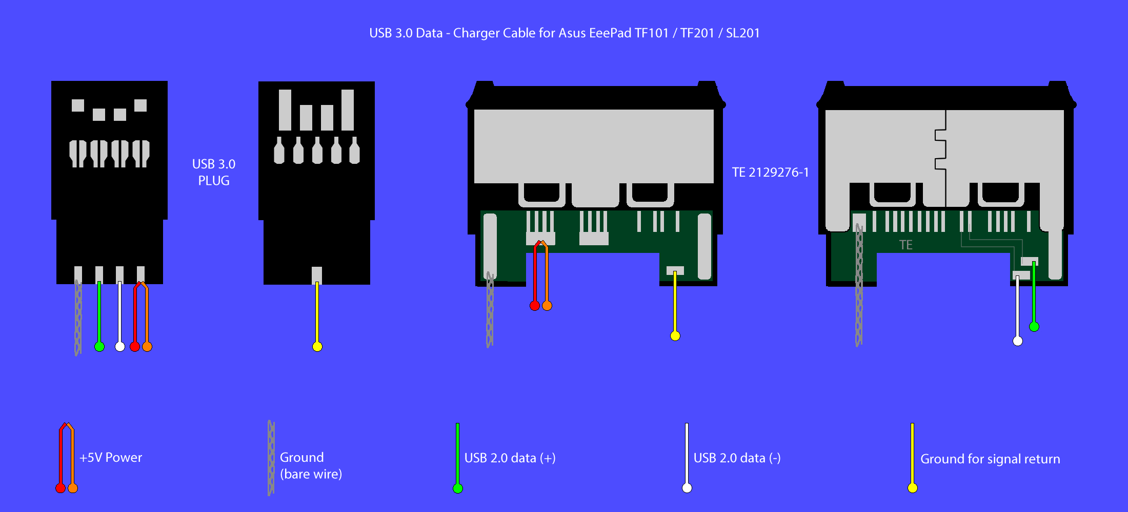 multi usb port circuit diagram | Wiring Diagram
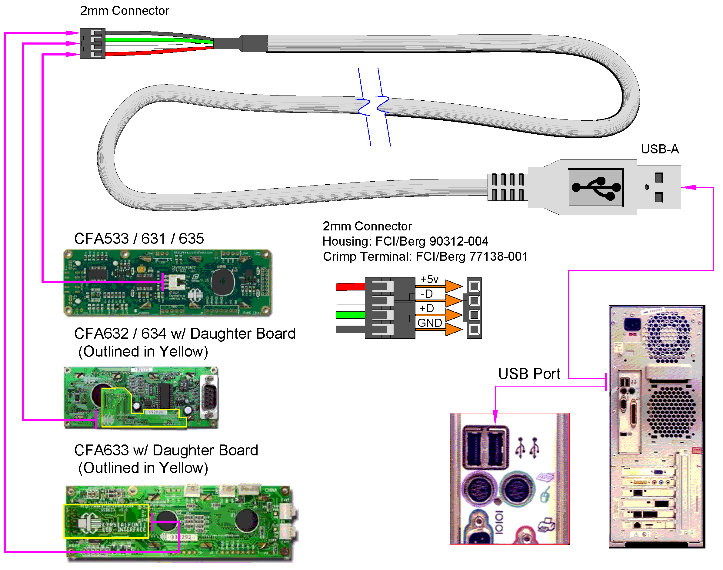 micro usb wiring colors | Wiring Diagram
 Usb Schematic Wiring Diagram
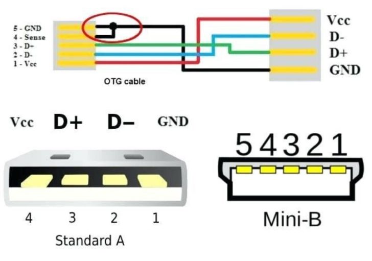 USB Wiring Diagram Standar A - Lexia's Blog
 Usb Pinout And Connection Diagram
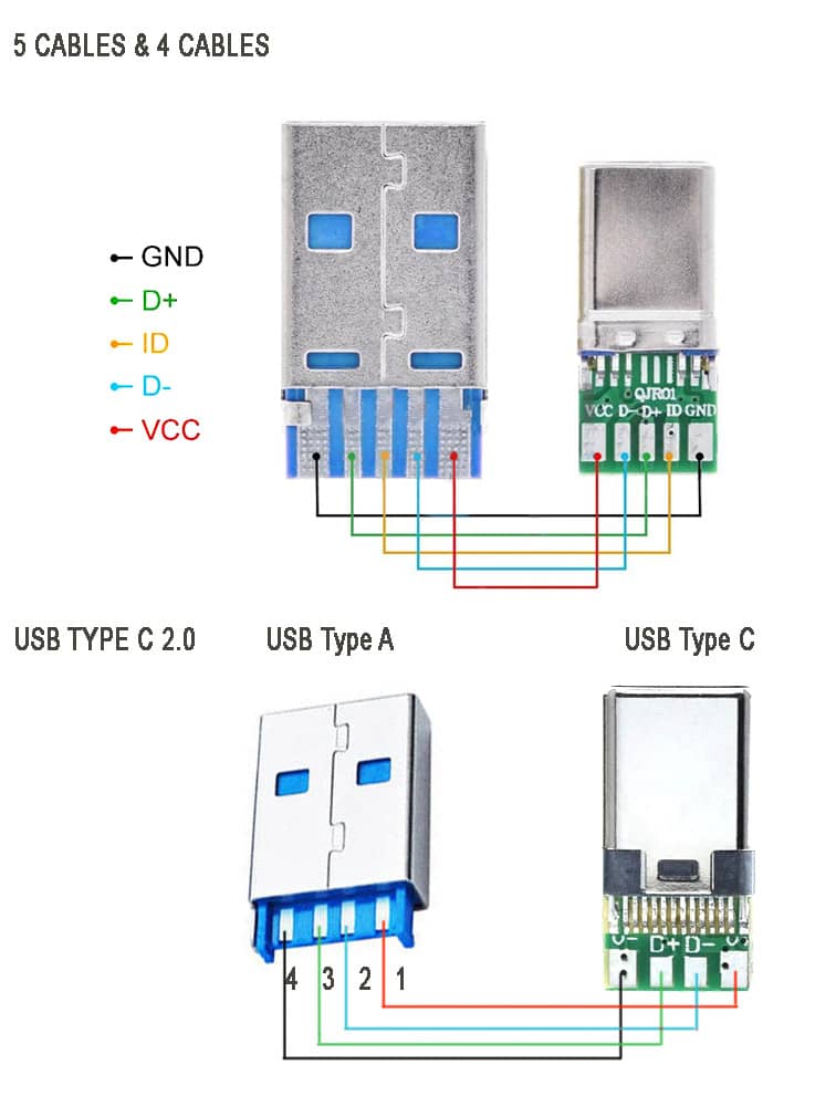 USB C Pinout - All USB 20-30 Type Pin Diagram - SM Tech
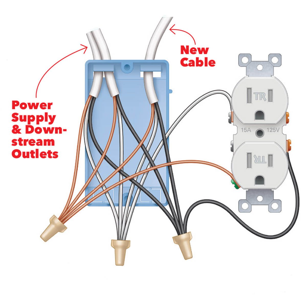 Wiring A Usb Outlet
