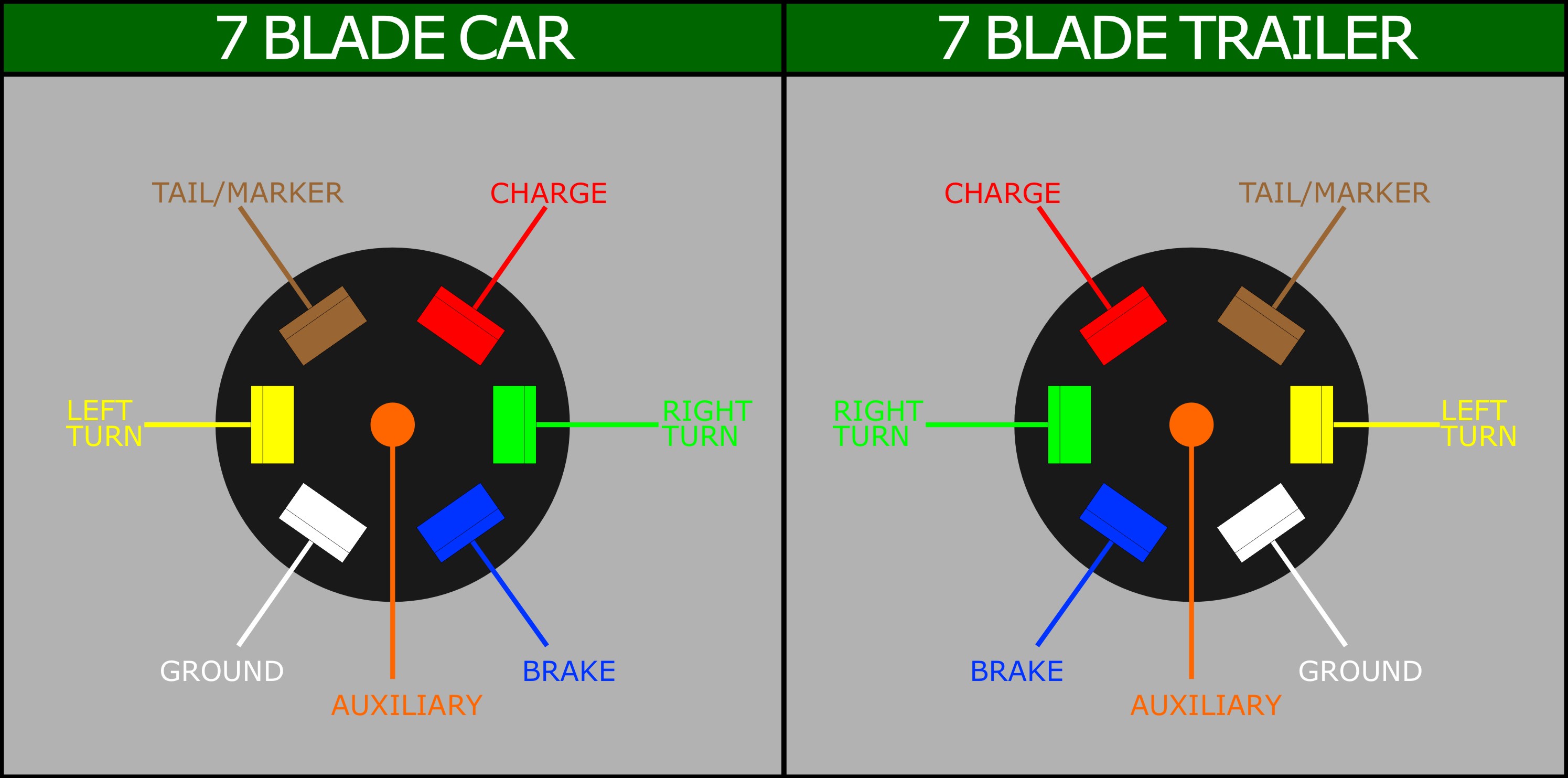
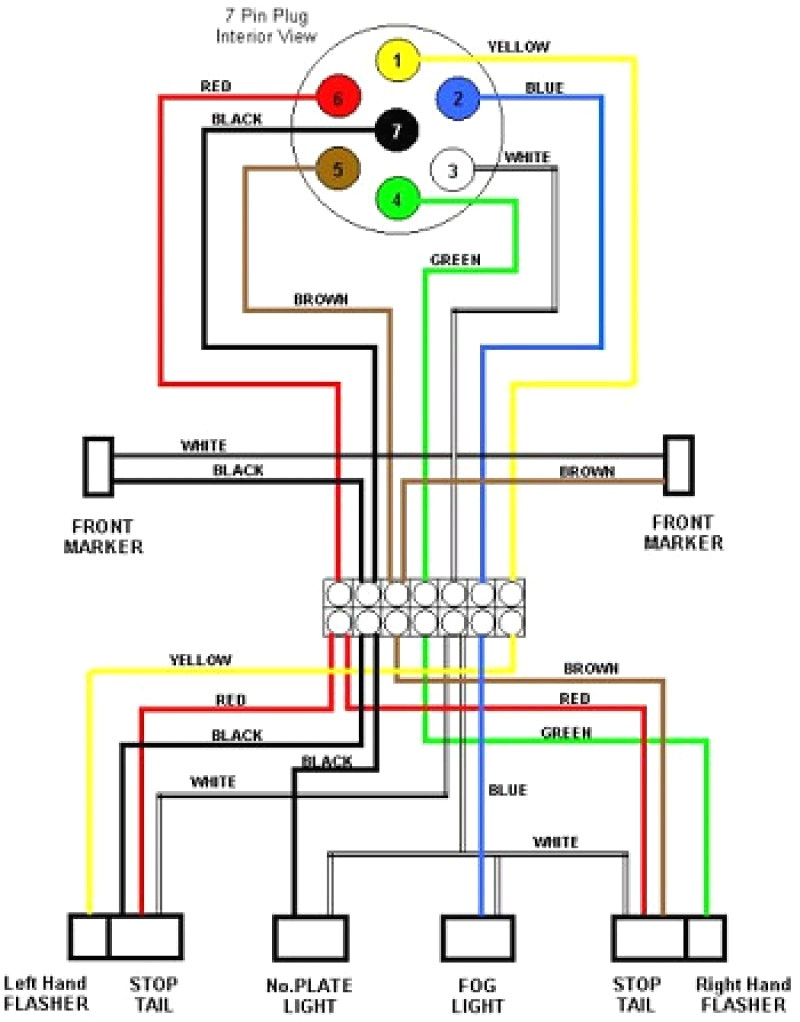
A 7 blade trailer wiring diagram brakes a visual representation the electrical connections wiring configuration required a trailer 7 pins a braking system. provides organized easy-to-follow layout how various components wires be connected ensure proper functioning the trailer's brakes.
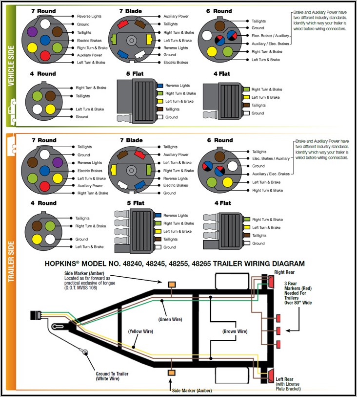 Use manufacturer trailer wiring diagram ensure wire to proper stud connection. Secure excess length wiring wire clips all connections made. a junction box not used, can cut ring terminals and heat shrink butt connectors join new 7-way harness to trailer's .
 What Size Wire Gauge Used a 7-Way Trailer Plug? minimum suggested wire size a 7-way trailer plug 16 gauge the turn signals, brake lights, reverse lights, running light wires. suggested minimum the ground, brake power, battery hot lead wires 12 gauge. the wire too thin, can overheat even catch fire carrying electrical current.
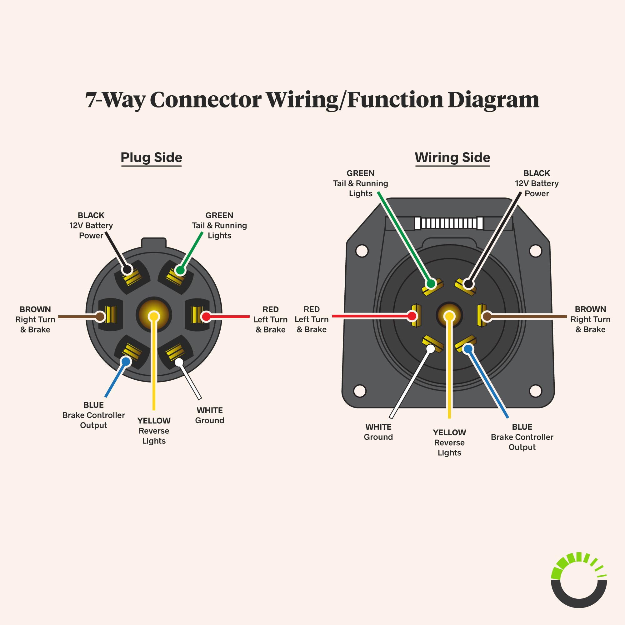
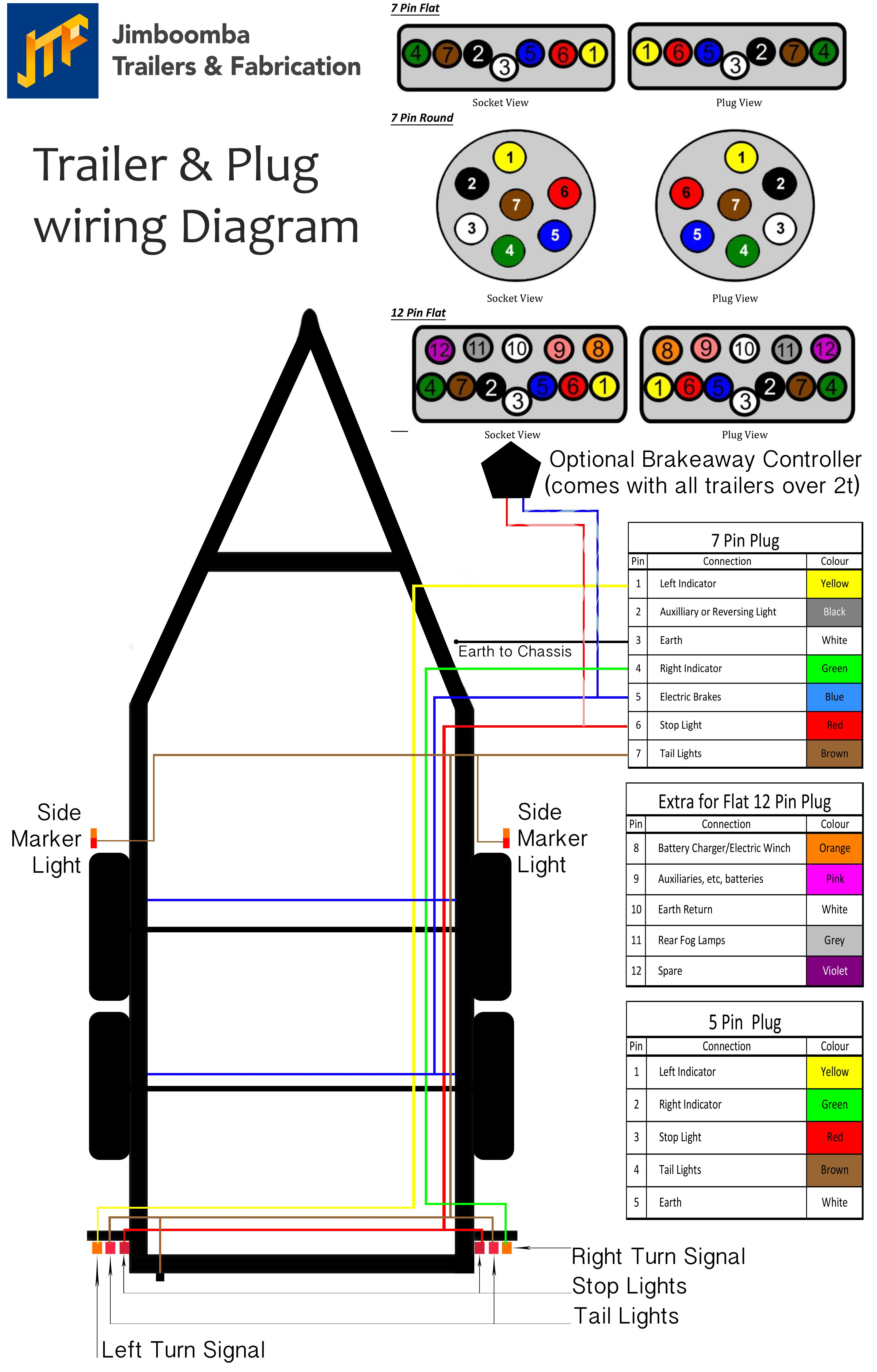
 The 7-blade connector commonly in trailer wiring systems, allowing the connection various lights, brakes, other electrical components a towing vehicle a trailer. diagram a visual representation the pins their functions the connector.
 C-55 electrical iri NG & acce SSO rie www.cequentgroup.com ©2010 Cequent Performance Products, P/N 98929-2011 Rev. A. 11/10 2011 WiriNG DiaGraMS NOTE: 7-Way Trailer wiring diagram represents wire location color is supplied to
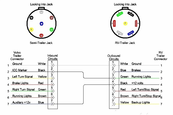 Understanding wiring diagram for 7 blade trailer connector essential ensuring proper installation functionality. Pin configuration: 7 blade trailer connector consists seven pins are numbered color-coded easy identification. pins arranged a circular pattern, the top center pin the ground.
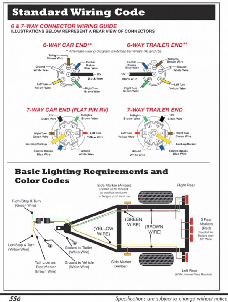
 The 7 Blade trailer plug a standard connector to connect electrical systems a trailer a towing vehicle. provides power the trailer's lights, brakes, other electrical components. Wiring a 7 Blade trailer plug correctly important it for proper communication the towing vehicle the trailer.
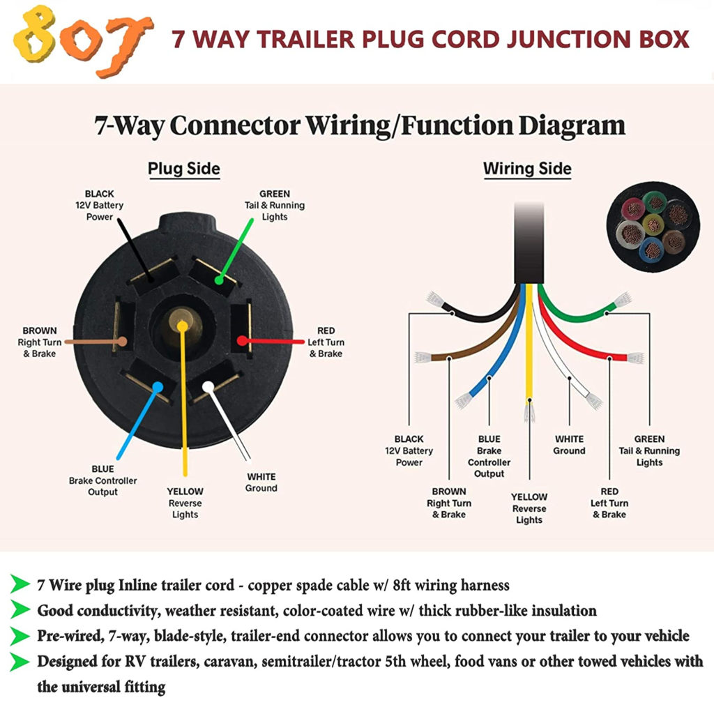 The Hopkins 7 Blade Wire Diagram a commonly wiring diagram for trailers a 7 blade connector. diagram helps guide installation connection the electrical components control trailer's lights, brakes, other functionalities.
 7 Plug Wiring Diagram Standard Wiring* Post Purpose Wire Color TM Park Light Green (+) Battery Feed Black RT Turn/Brake Light Brown LT Left Turn/Brake Light Red Trailer Electric Brakes Blue GD Ground White Accessory Yellow is most common (Standard) wiring scheme RV Plugs the used major auto manufacturers today.
 If are at inside the trailer connector the wires mount the terminals starting the notch the top working clockwise: 1:00 Black 12 volt power 3:00 Green Right Turn Brake 5:00 Blue Brake Controller 7:00 White Ground 9:00 Yellow Left Turn Brake 11:00 Brown Tail Running Lights Center Purple is .
 Wiring Diagram For 7 Blade Trailer Plug - 7 Way Rv Trailer Connector
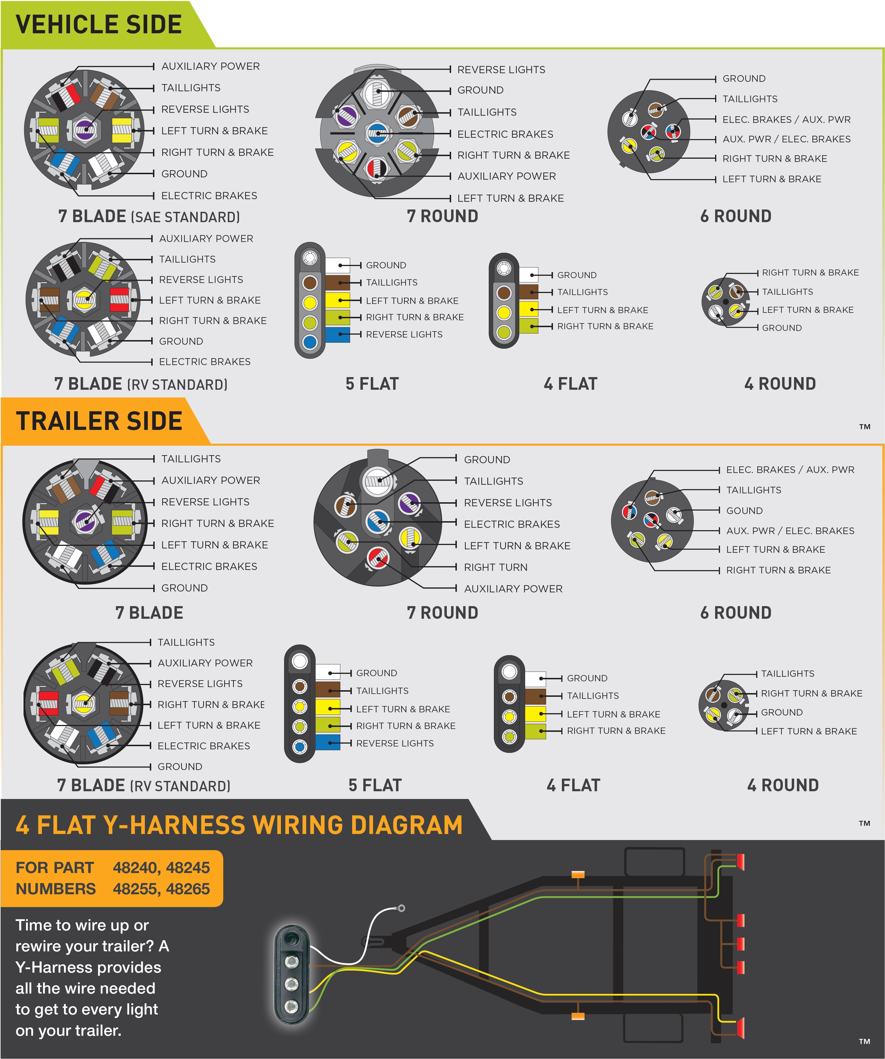 7 Blade Trailer Connector Wiring Diagram - Cadician's Blog
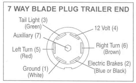 Seven Blade Trailer Plug Wiring Diagram
 Pace Trailer 7 Blade Wiring Diagram
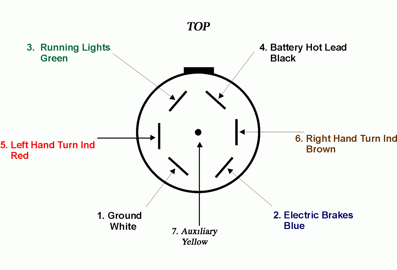 7 Blade Trailer Wiring Diagram - Cadician's Blog
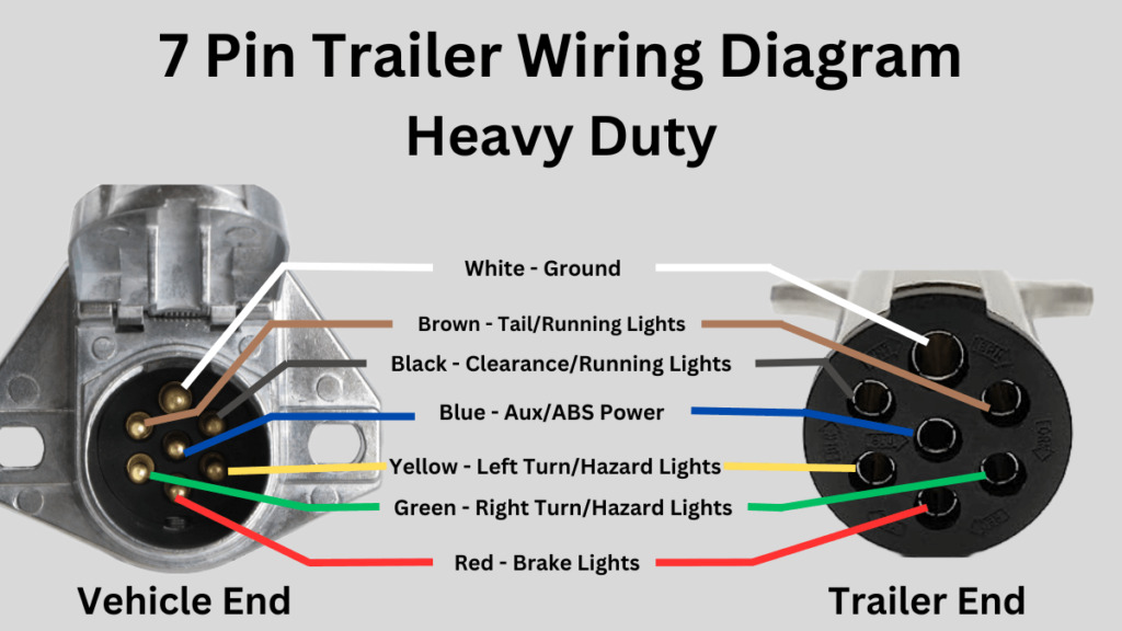 How To Connect Your 7 Pin Trailer Wiring Easily (Diagram Included
 Install 7 Blade Trailer Plug
 7 Blade Trailer Connector Wiring Diagram - Cadician's Blog
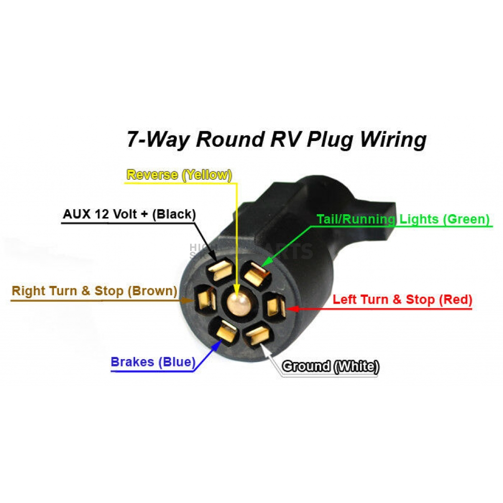 7 blade rv trailer plug wiring diagram - IOT Wiring Diagram
 7 Blade Trailer Plug Wiring Diagram: A Step-by-Step Guide
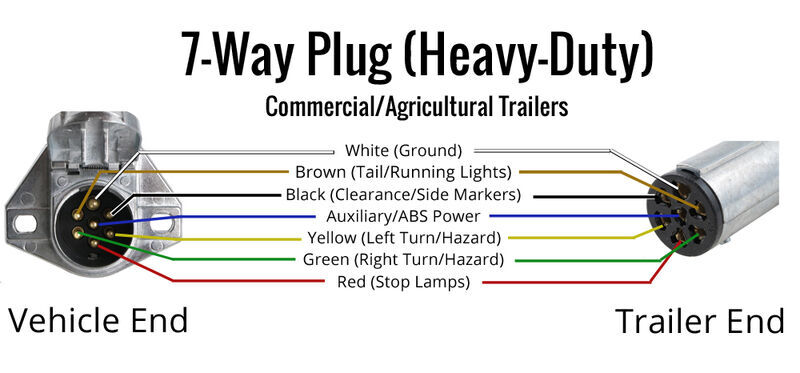 7 Blade Trailer Plug Wiring Diagram Gmc - Wiring Diagram and Schematic Role
