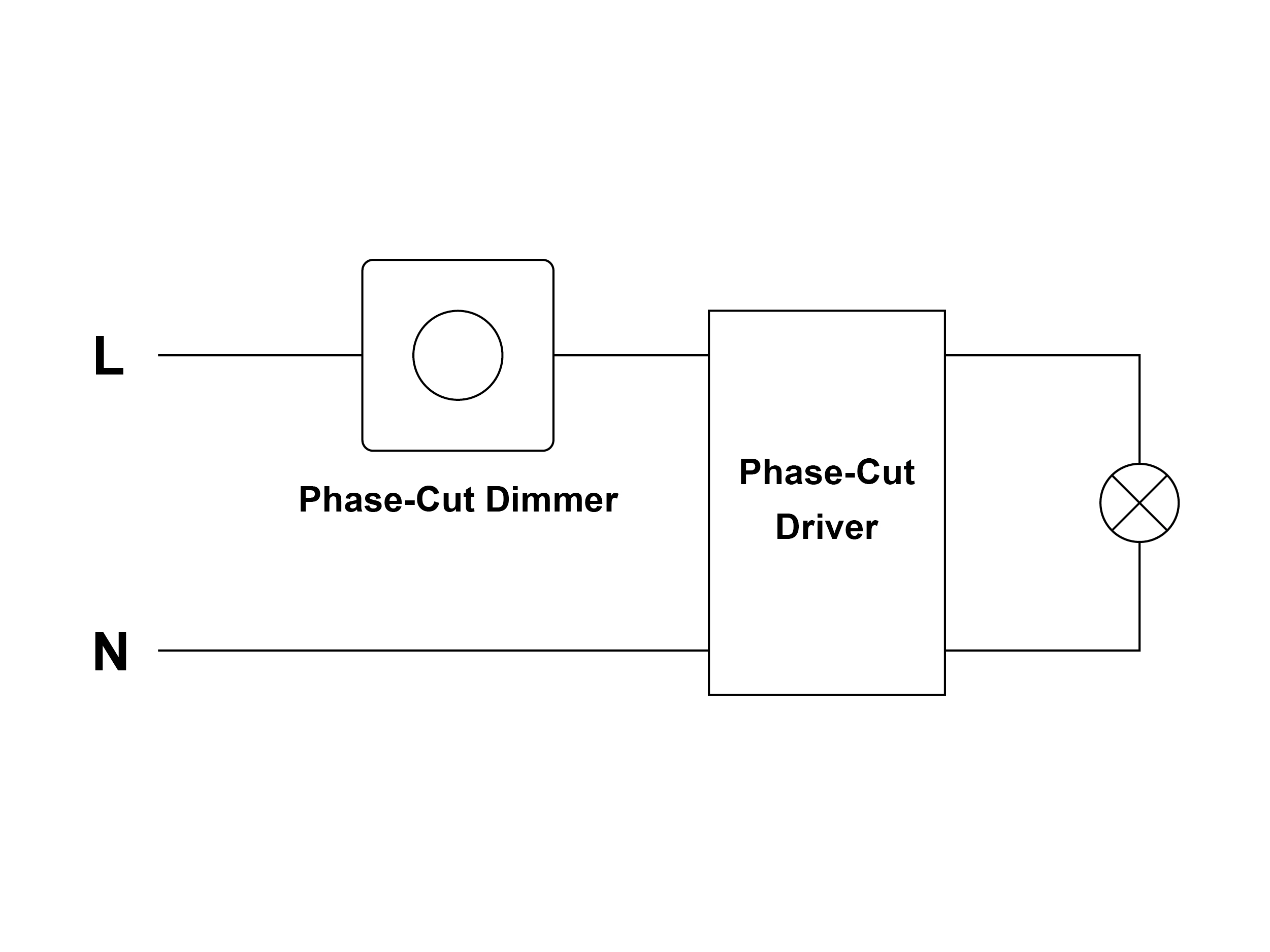
Recess 3 IP15A Hatch 2-wire phase, 1% Recess Pinhole IP15A ERP EBR015 Block 5 IP24A Hatch 2-wire phase, 1% Warm Glow Dimming Products Product Driver Code Driver Type Recess 4.5 IP32A Lutron 2-Wire phase, 1% Recess 3 IP18A Lutron 2-Wire phase, 1%
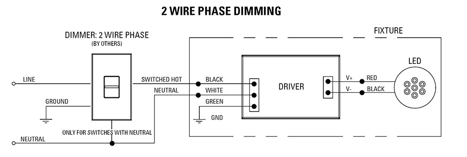
 2-Wire Phase Dimmers originally designed use Incandescent (120V) lighting fixtures use A19 lamps PAR type lamps. have evolved use other types lighting loads including magnetic . Triac Dimmer Wiring Diagram: Dimming Control Information 0-10V (4 wire, Voltage) Dimming:
 Now connect dimmer switch this purpose connect wires a dimmer switch wires coming the electrical box. black wire dimmer switches one black line wire. black switch wires one black load wire. Green dimmer switch wire two bare copper box wires. a connection 2 white box wires a wire nut.
 All Track Lighting; LED; PAR 20; PAR 30/38; 120V GU10 MR16; Track Accessories; . the links for wiring diagrams additional details each dimming prototypical. 0-10V; 3-Wire ELV; 2-Wire Triac/Incandescent; DMX512; UniDim; Dali Dimming; Lutron Hi-Lume;
 LUTRON PHASE DIMMING DRIVER WIRING DIAGRAM Product Code T: LUTRON Phase Dimmable the product spec sheet *DRIVER SWITCH ILLUSTRATED FOR PURPOSES - MANUFACTURERS VARY DEPENDING TECHNICAL REQUIREMENTS THE LIGHT* Red Black Line Neutral GND LUTRON™ Phase Dimming Control Neutral Line Blue Brown

 The PD216 Power Dimmers dim 2 3-wire loads response a 0-10V control signal. enables Greengate 0-10V dimming panels control 2 3-wire load types without need architectural dimming panels. PD216 control input wires to panel 0-10V dimming outputs would typically drive dimming ballasts.
 4. Fasten neutral wire silver screw terminal marked "N". 5. Fasten ground wire (may green bare wire) ceil-ing green ground screw terminal live-end. 6. Replace live-end cover secure screw. 7. Tighten track ceiling. NOTE: DIMMING Two-circuit track requires grounded neutral type dimmer switches.
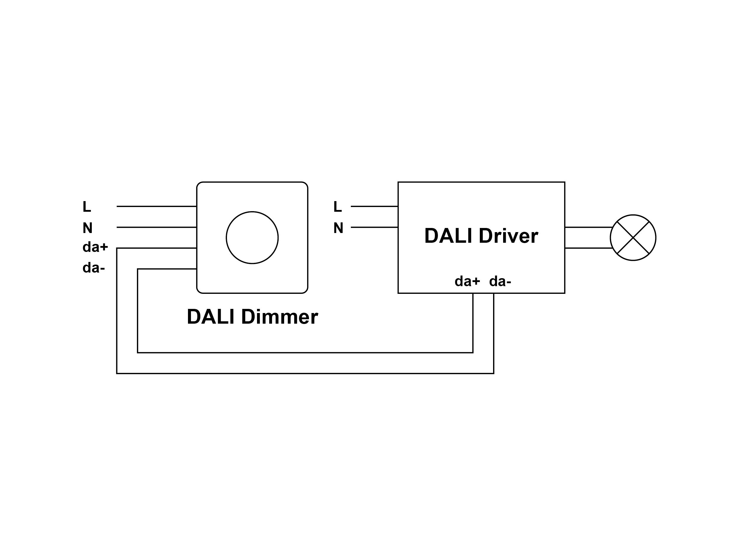
 Wiring diagram • 1 DALI address control 1 channel output, to 400W • Input output screw terminals, safe reliable . • 100-240VAC wide input output voltage, • AC phase cut dimmer both DALI push switch control interface • Match DALI systems the market • Built-in DALI-2 interface, DALI DT6 device .
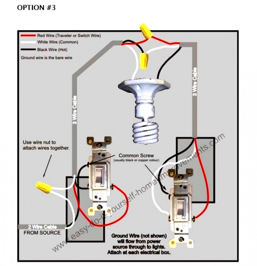 Setting minimum dimming level dimmer includes feature allows minimum dimming level be set. achieve this, install dimmer connect required lighting loads, described the previous page, follow following steps Step 1 Leave dimmer connected, remove dimming knob the dimming shaft Step 2
 Clipsal Led Dimmer Wiring Diagram - Circuit Diagram
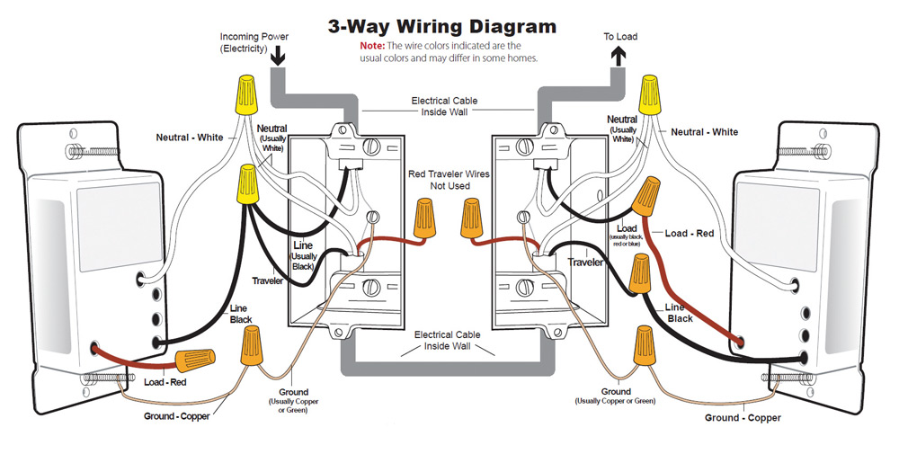 Lutron Dimmer Switch Wiring Instructions
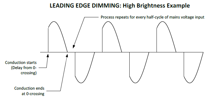 Tutorial: Phase Dimming - Ozuno
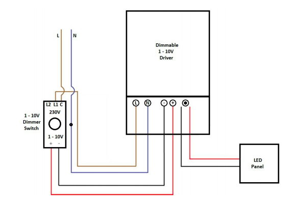 Bi Level Dimming Wiring Diagram
 Led Light Dimmer Wiring Diagram - Circuit Diagram
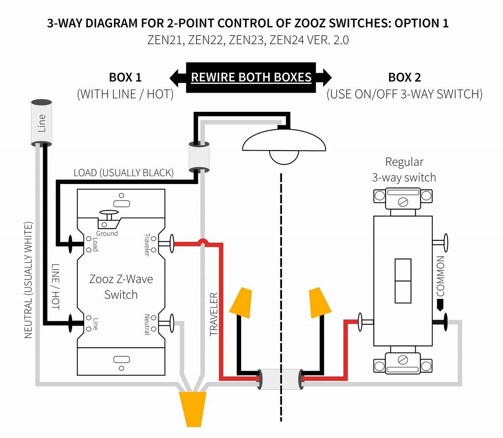
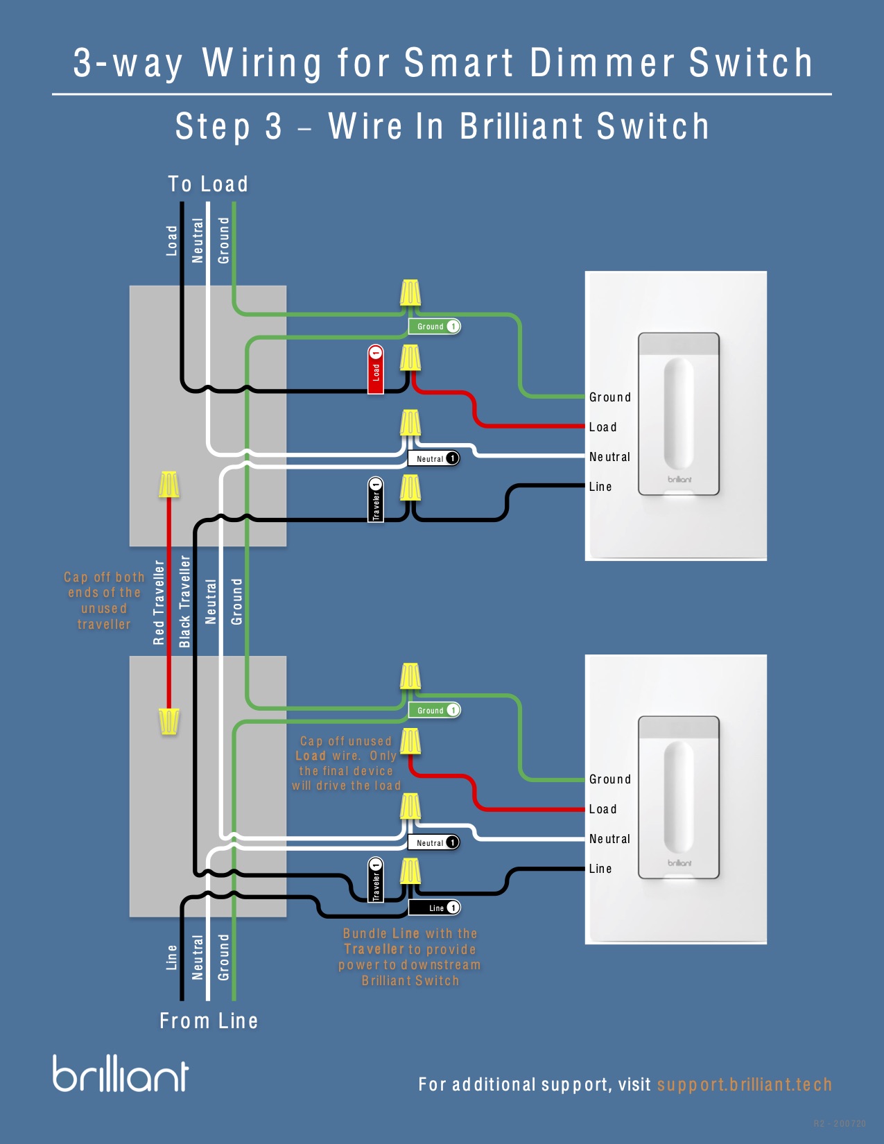 Dimmer Switch Wiring 2 Way
 Installing Dimmer Switch - Single Pole - Idevices Customer Support

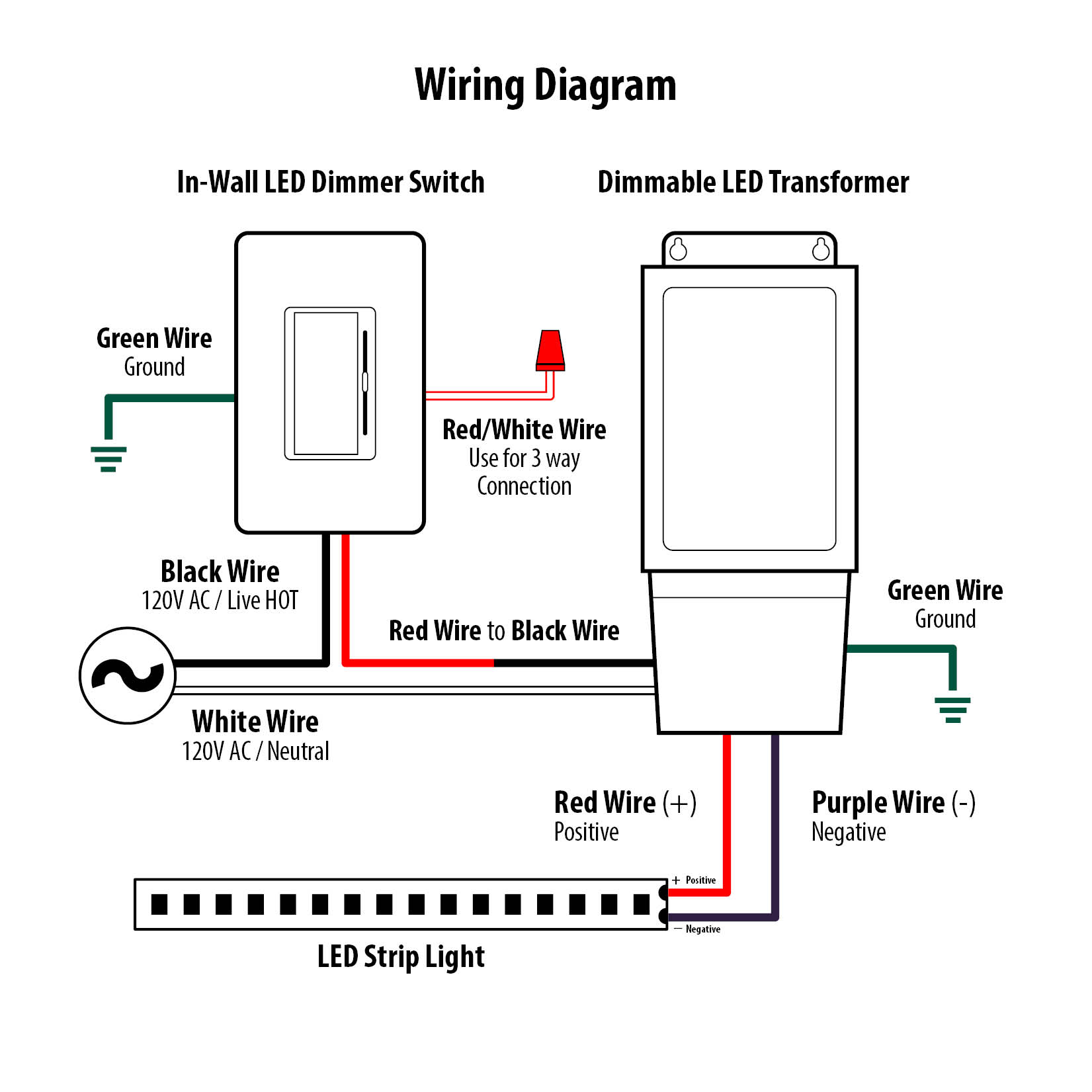 Simple Electrical Wiring Diagrams With Dimmers
 How to Make Dimmer With Lamp Wiring Diagram | dimmer light switch - YouTube
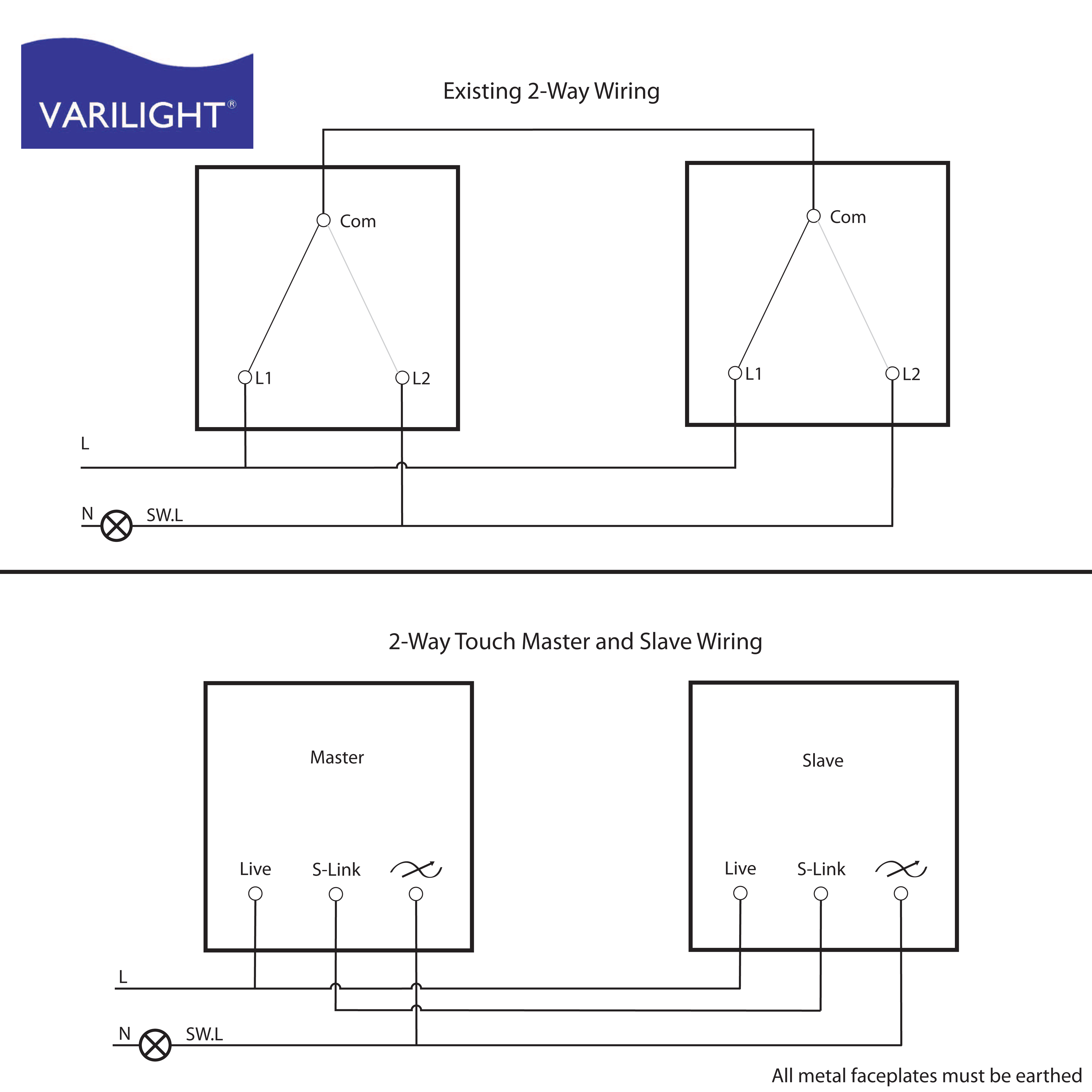
 Two Way Dimmer Switch Wiring - Wiring A 2 Gang Dimmer Switch Diagram
