CROWN 4-PIN CONNECTOR WIRE ILLUSTRATION PIN COLOR WIRE BRAID B RED BLACK WHITE NOTE: 4 PIN Load Cells/Weigh-Bars not intermixed 5-PIN Load Cells. . Scale-Tec POINT system utilizes 8 PIN connector (AT06-08SA-SR2BK) supports following interfaces: Serial (RS232) (COM1 COM2) CANBus (ISOBUS) POWER 12v DC 3 .
 OK, at 5 pin connector the 69232. is small mark shaped this: > represents pin 1. Pins 1 5 track power frm 2-4-0 loco the tender go the rear tender conmnector a polyfuse lighting passenger cars for sound car.
 scale 2:1 2 5 3 1 6 7 1 9 connector pin assignment m23 12 pole front side view 1 1 8 10 4 2 notes specification (bom - item 9) printed a5 size sheet contacts 9 10 connected same wire 8 white green yellow grey pink red black violet brown green/yellow blue wiring diagram pin 1 pin 2 pin 3 pin 4 pin 5 pin 6 pin 7 pin 8 pin 9
 The cable from indicator the plug the side the floor scale. cable a 5-pin connector both ends. 20 feet. Waterproof. Additional information. Weight: 1 lbs: Dimensions: 9 × 9 × 4 . cable a 4-pin connector one and bare wire the other. 20. Read More. Add cart; Compare. Add Wishlist. Add .
 Mark wire +5V. pin is opposite Vcc the comparator's Ground pin (third the top the side). Repeat steps and mark wire the lowest resistance "Ground" pin the is connected the ground. your scales only wires (plus braided shield), are done.
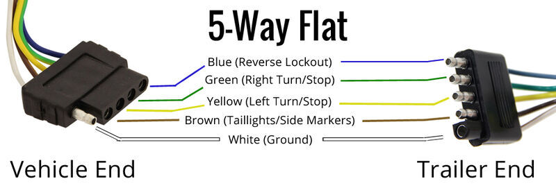 In summary, 3 phase plug wiring diagram 5 pin a valuable tool provides visual representation the electrical connections circuitry a three-phase system. guides electricians properly installing connecting electrical equipment, ensuring safety efficiency. . as industrial machinery large-scale .
 FEATURES Replacement cables indicators, scales scoreboards is standard replacement interface cable the OP-900, LP-7510, BB-7510, BB8100SS similar indicators. cable a 5-pin connector one and bare wire the other, is wired the junction box. 20 feet. Waterproof.
 4.Wiring Diagram: pin -, + S LED module connected the pin G, 5V D10 port expansion board. . the final lesson, will sum the comprehensive features electronic scale. 2.Flow Chart: 3.Wiring Diagram: 4.Test Code: 5.Test Result: (1)Set Calendar. Plug power, turn switch, screen shows time .
 DME 10 AMP 5 PIN SCREW TERMINAL CONNECTOR WIRING DIAGRAMS Wiring Diagrams MALE CKPTIC-I CKPTM-I CKPTM-IL SSI-I ESH WIRING DIFFERENCES ESH FEMALE CKPTOC-I CKPTF-I CKPTF-IL Note: SSH North America Standard Wiring Deg ESH European Union Standard Wiring Deg 5 PIN 10 Amp Connector SSH WIRE CONNECTIONS NOTE .
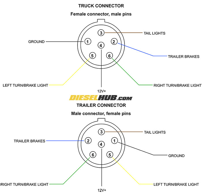 Alternative: CP-1034-ND (locking plug) CP-1234-ND (locking receptacle) Notes: 1) Pin numbers in RED text 2) Views show mating faces prevent "noise" the signal, shielded 4-conductor cable be to connect load cell the amplifier box. example: Digikey p/n W504-100-ND A131-100-ND 4 3 2 4 3 1 2 1 OR
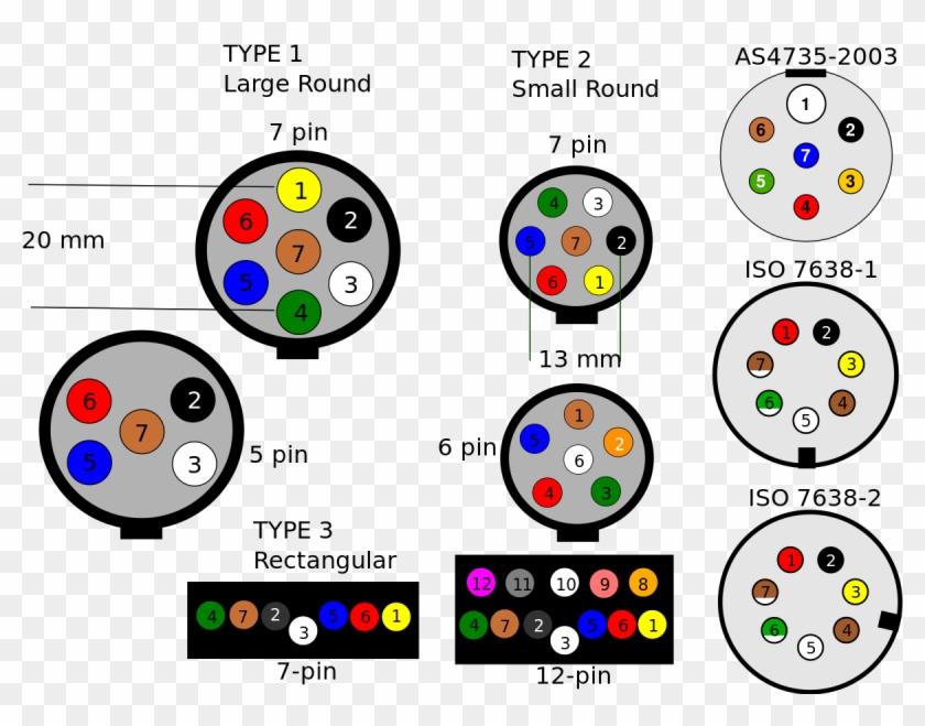 Three Phase 3 5 Pin Plug Wiring Diagram - Wiring Diagram and Schematic
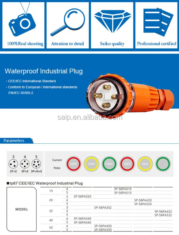 5 Pin Plug Wiring Diagram - Database - Faceitsaloncom
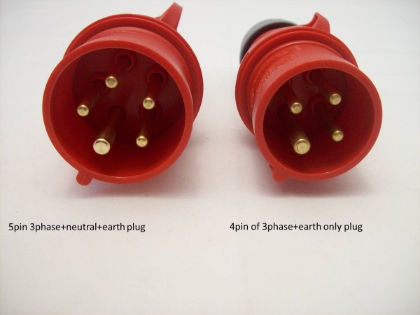 5 Pin Plug Wiring
 3 Phase 5 Pin Plug Wiring Diagram - Wiring Diagram
 5 Pin CDI Wiring Diagram (Pictured AND Explained!) - Off-Road Official
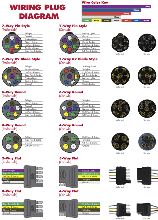
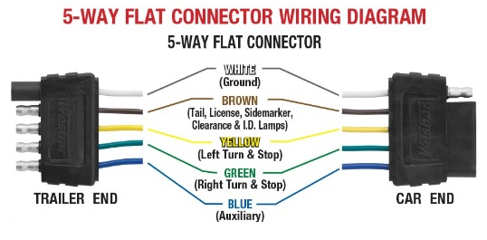 Trailer Wire Diagram 5 Pin
 Chinese 5 Pin CDI Wiring Diagram (Pictured & Explained) - Off-Road Official
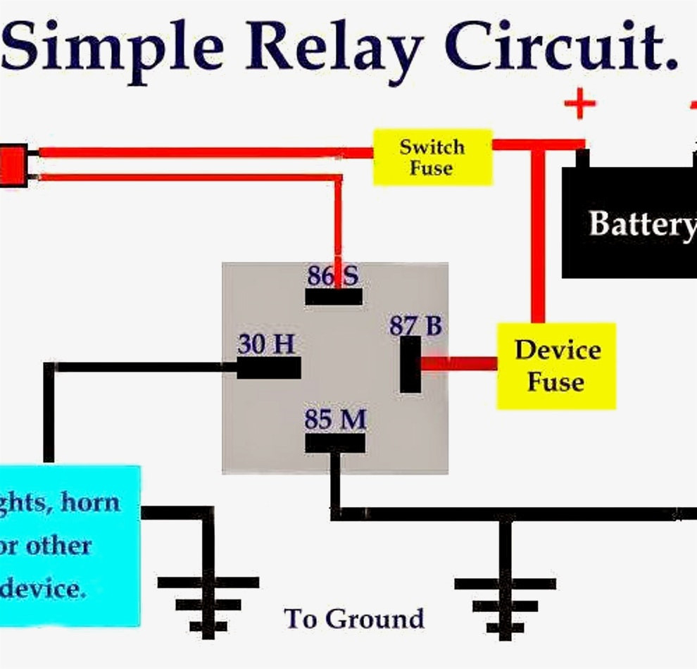 How To Wire A 5 Pin Relay Switch Diagram
 7 Pin Plug Wiring Diagram Uk Re-doing The Power Wiring 2 Pin Plug
 How To Make 5 Pin Relay Wiring Diagram | Relay - YouTube
 How To Test A 5 Pin Relay (With Wiring Diagram)
