Overall, 240 volt single phase motor wiring diagram an essential tool understanding working these types motors. provides visual representation the electrical connections components, making easier install, troubleshoot, maintain motor system. Step-by-Step Guide Wiring 240 Volt Single Phase Motor
 Permanent Split Phase Capacitor Motor Wiring Diagram. as name implies, single phase motor diagram work a split phase generated a capacitor. capacitance the capacitor the reactance the winding shift phase some extent. is permanent capacitor single phase motor wiring diagram.
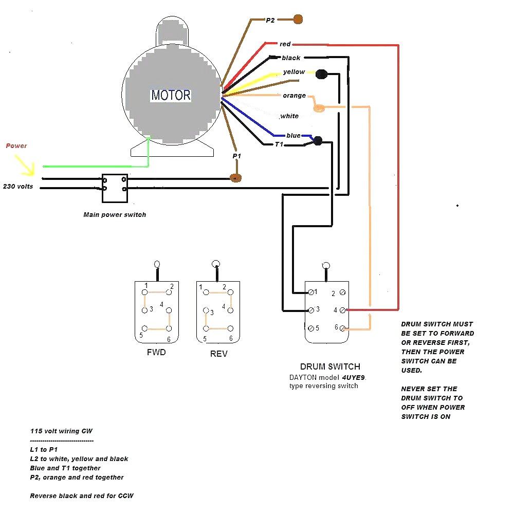
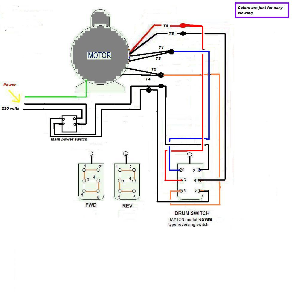 Single Phase Electric Motor Wiring Diagrams, Terminal Connections, Frame Sizes, Electric Motor Information - Updated March 20, 2024 . SPLIT PHASE CAPACITOR RUN SINGLE PHASE MOTOR DIAGRAM. . winding arrangement only as starting torque 120 volts on 240-volt connection. Top Page.
 4. Route wires the proper size T1 T2 the RC2W, the conduit the siren motor leads. Page 20: Section Iv - Circuit Description SECTION IV CIRCUIT DESCRIPTION 4-1. SIREN CONTROL DESCRIPTION Model RC2W used operate Model 2 Siren. RC2W a motor starter switches power the Model 2 siren.
 building. a result, siren be installed almost situation. high efficiency these siren models enables to produce high sound level making moderate demands the power source. Siren Description Model 2 Siren a 102 dB single-tone siren. Model 2 siren mechanism enclosed a sheet metal housing.
 The wiring diagram a single phase 2 speed motor typically include following components: main winding, start winding, motor switch, a capacitor. main winding responsible the normal operation the motor its speed, the start winding used provide initial torque required start motor .
 The motor a Century single phase 2 hp thermally protected capacitor start unit can wired either 120 240 volts. . to diagram the motor's label, I'm sure to the connection the motor feed the pressure switch. . 120v. wire 240v, white brown wires shifted .

 Essential Components a 240 Volt Single Phase Motor Wiring Diagram wiring 240 Volt single phase motor, it's important understand core elements the type motor wiring diagram. Motor Switch: motor switch used turn power and off. switch two positions, "on" position the "off" position.
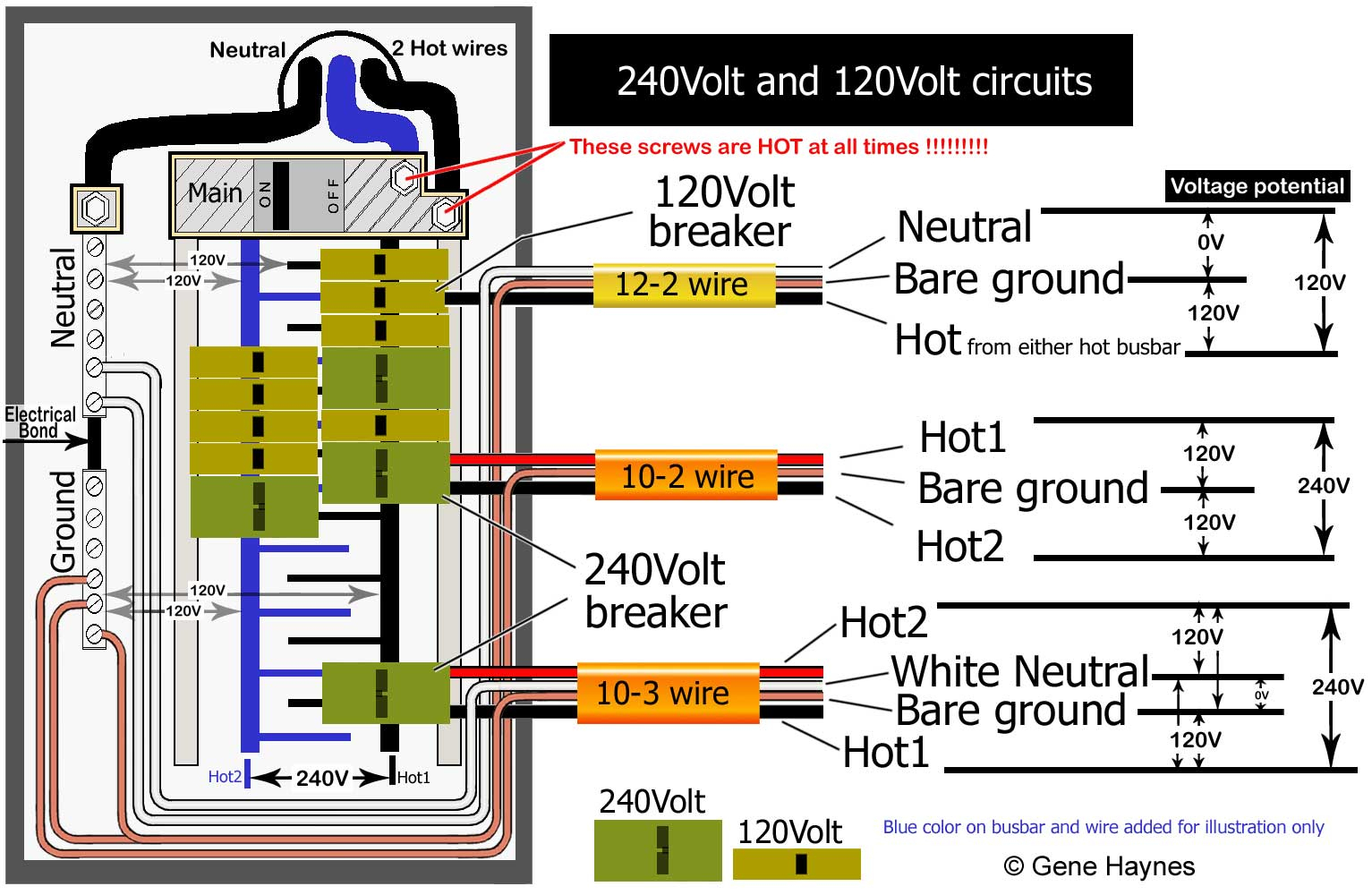
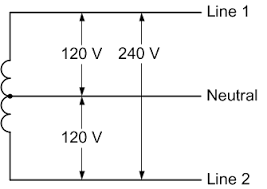
 Order 240 volt meter. diagram shows to wire for 120V. 🔗 Click to view print full size diagram. . print full size diagram. 2, 3 Phase - Form 12S Click links to download print full size diagrams: 🔗 Single Phase Network, 2 Phase , 3 wire, 120/208 volts. 🔗 Phase, 3 Wire 277/480 volts .
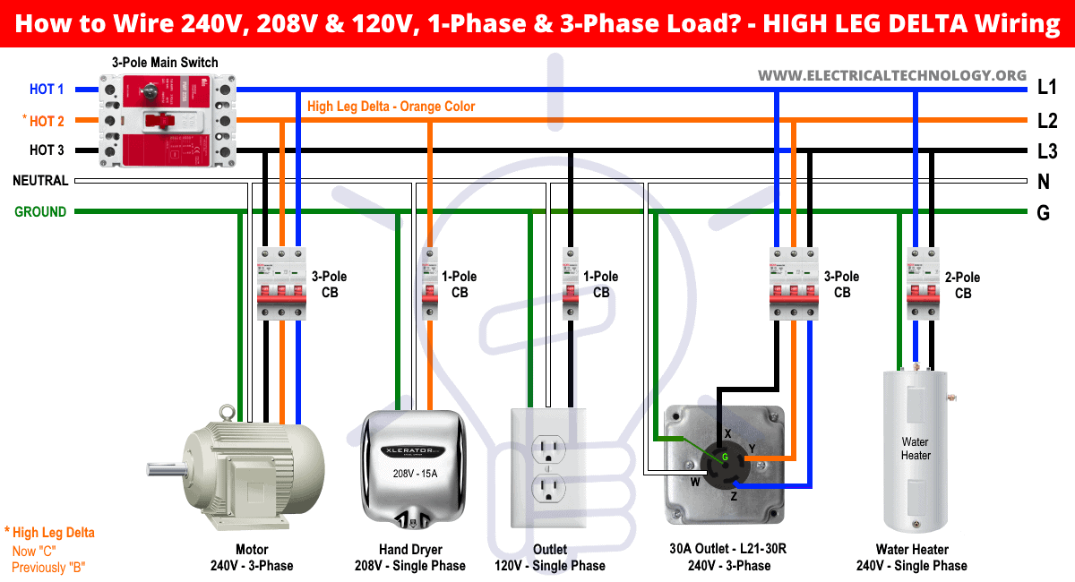 Single Phase 240v Breaker Wiring Diagram
 240v Single Phase Wiring Diagram
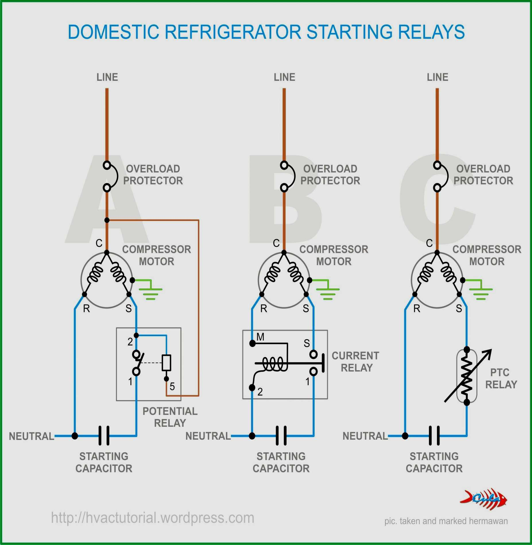 240v Motor Wiring Diagram Single Phase
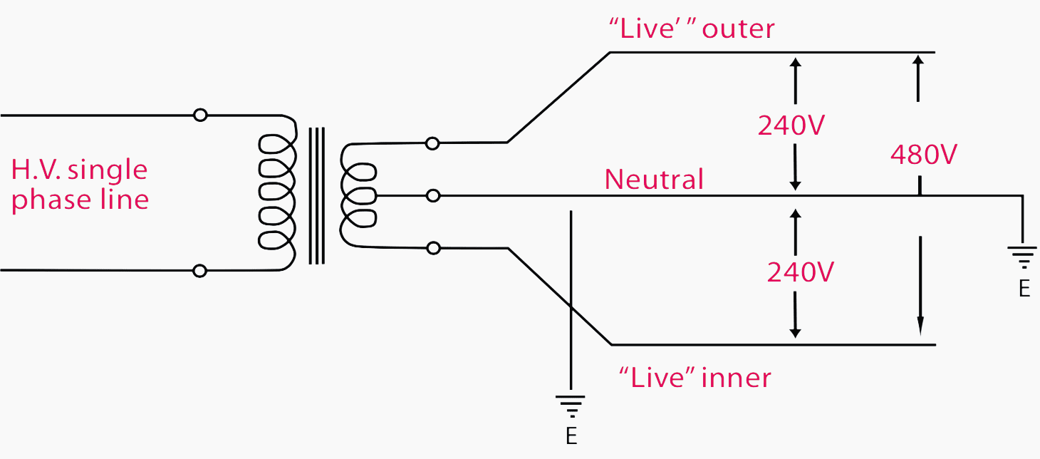 How To Wire 240v Single Phase
 Residential 240v Single Phase Wiring
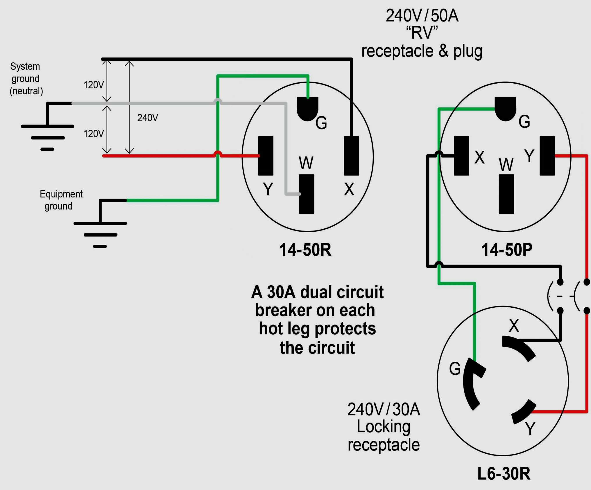 Wiring Diagram 240v Outlet
 Single Phase 240v Wiring
 240v Single Phase Wiring Diagram
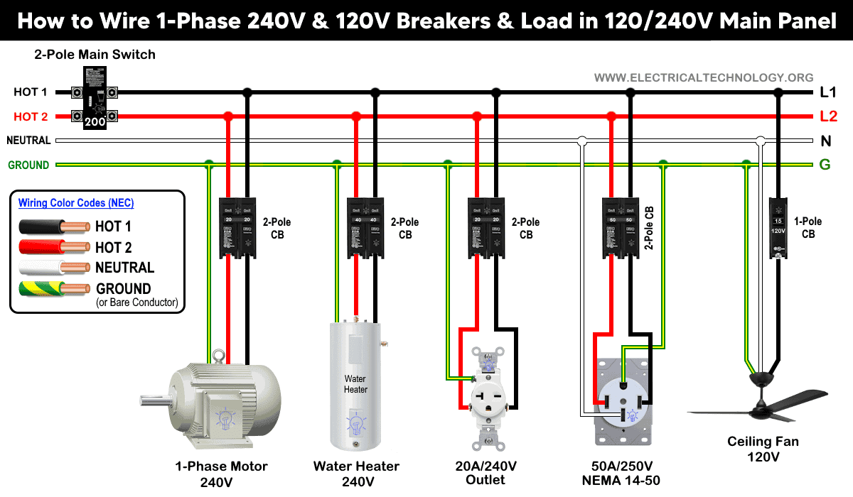 Single Phase Electrical Wiring Installation in Home - NEC & IEC
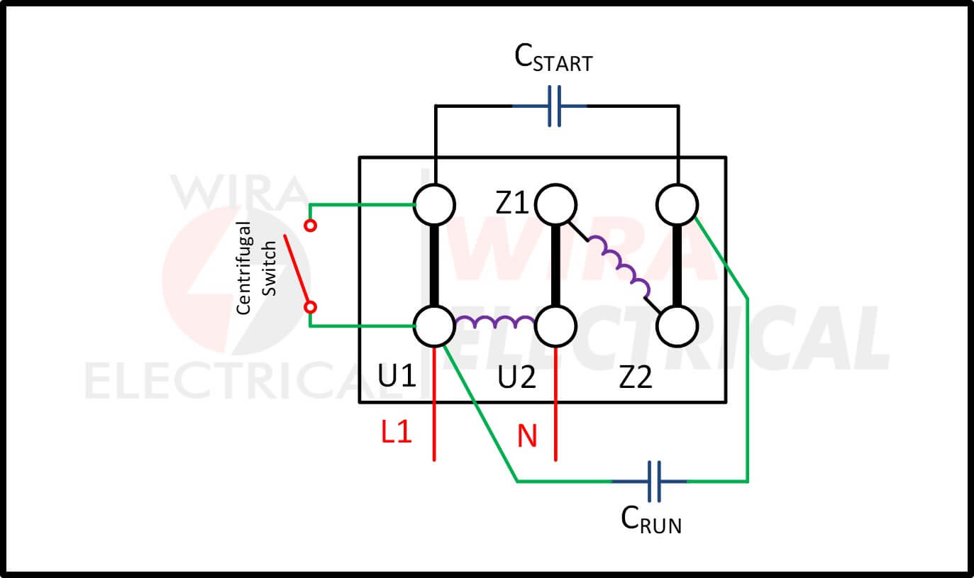 Single Phase 240v Motor Wiring Diagram
 Single Phase 240 Volt Wiring
