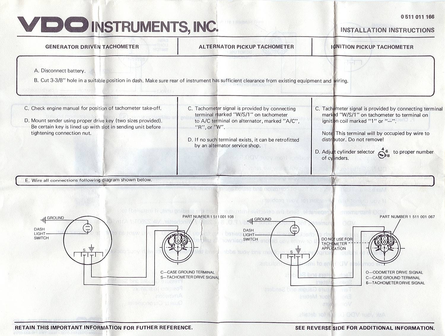
A VDO tachometer wiring diagram a schematic representation the electrical connections to install operate VDO tachometer a vehicle. diagram typically included the product's installation manual can found online. shows specific wires need be connected the vehicle's ignition system, .
 Tachometer, Display 13 GB 14 Connector set, 8-pin A2C59510850 30 - terminal 30 - steady-state 12 15 - terminal 15 - connected (ignition) 58 - terminal 58 - lighting 31 - terminal 31 - ground Designations the wiring diagram: 8-pin connection F1 - fuse 5A quick-response C1 - 8-pin MQS connector must comply the .
 VDO Tachometer Installation Instructions Subject: Revision: VDO Programmable Tachometer Installation Instructions 10/05/04 B Revision Date: Standards No. 5000041-02 Page 2 4 Date Originated: 3.0 Wiring Tachometer 1. Disconnect vehicle battery ground performing wiring. Prepare insulated 1/4"(6.3mm) spade terminals use.

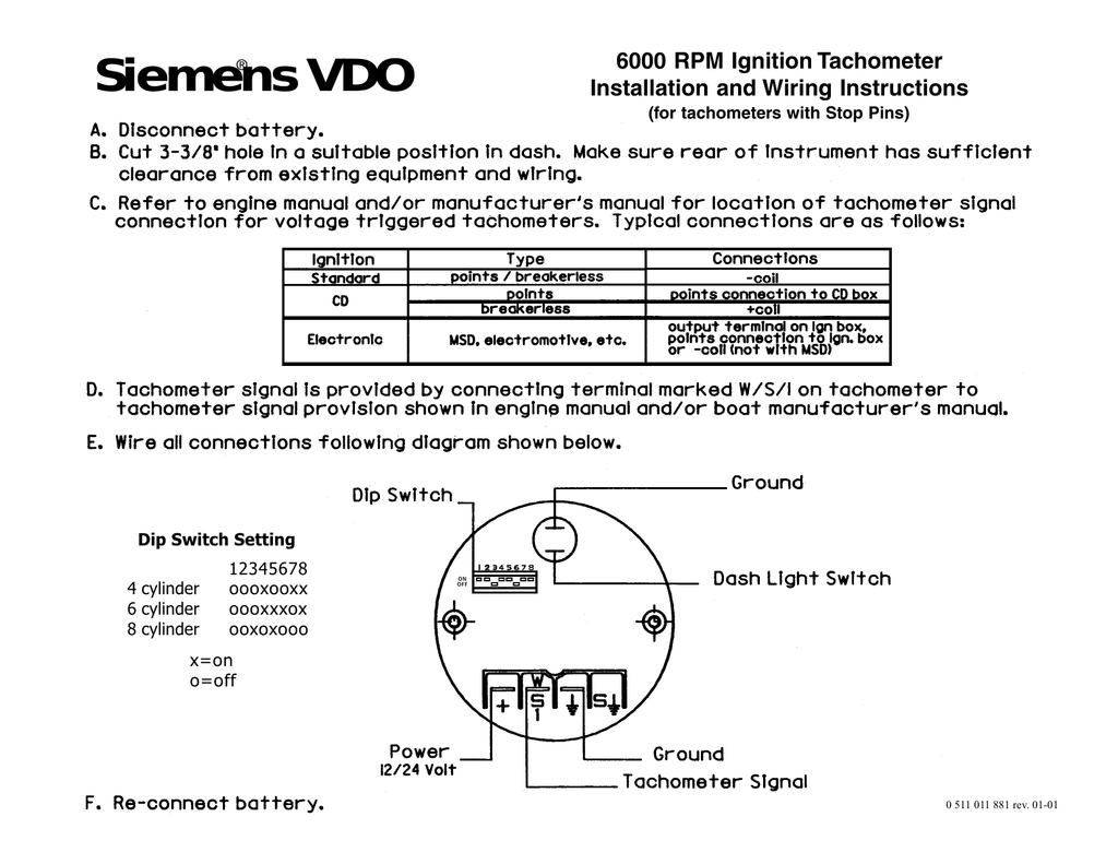 S Tachometer signal input (+) - Ground (-12V) signal (-) Parts List Item Description Qty 1 Gauge 1 2 Clamp & nuts 1 3 Instruction sheet 1 Read instructions before installation. not deviate assembly wiring diagram. disconnect battery ground making electrical connections.
 E) calibrate (Diagrams & F) mounting it. all applications, start here. [text continues] D+ ˘ˇ ˆ˙ B+ B+ D- ˝˛˚ ˙ ˝˜˚ ˙ ˝ ˚ ˙ˆ ˇ ˇ ˙ ˇ ˙! "˙ Diagram Proper wiring the VDO Programmable Tachometer typical ignition systems ˘ˇˆ ˙˘ ˝ˇ ! "˙ Diagram Fine adjustment the VDO .
 VDO Tachometer Hourmeter 85 mm; . Hall-Effect Sender Volkswagen (2004) Hall-Effect Sender Wiring & Testing (2005) Inductive Sender (2011) Instrument Kit (Electric Speedometer) Installation & Wiring (2009) . ViewLine 52mm Wiring Diagram (2014) Viewline Level Gauges 12/24 Volt (2011) Viewline Level Gauges 52mm (2008)
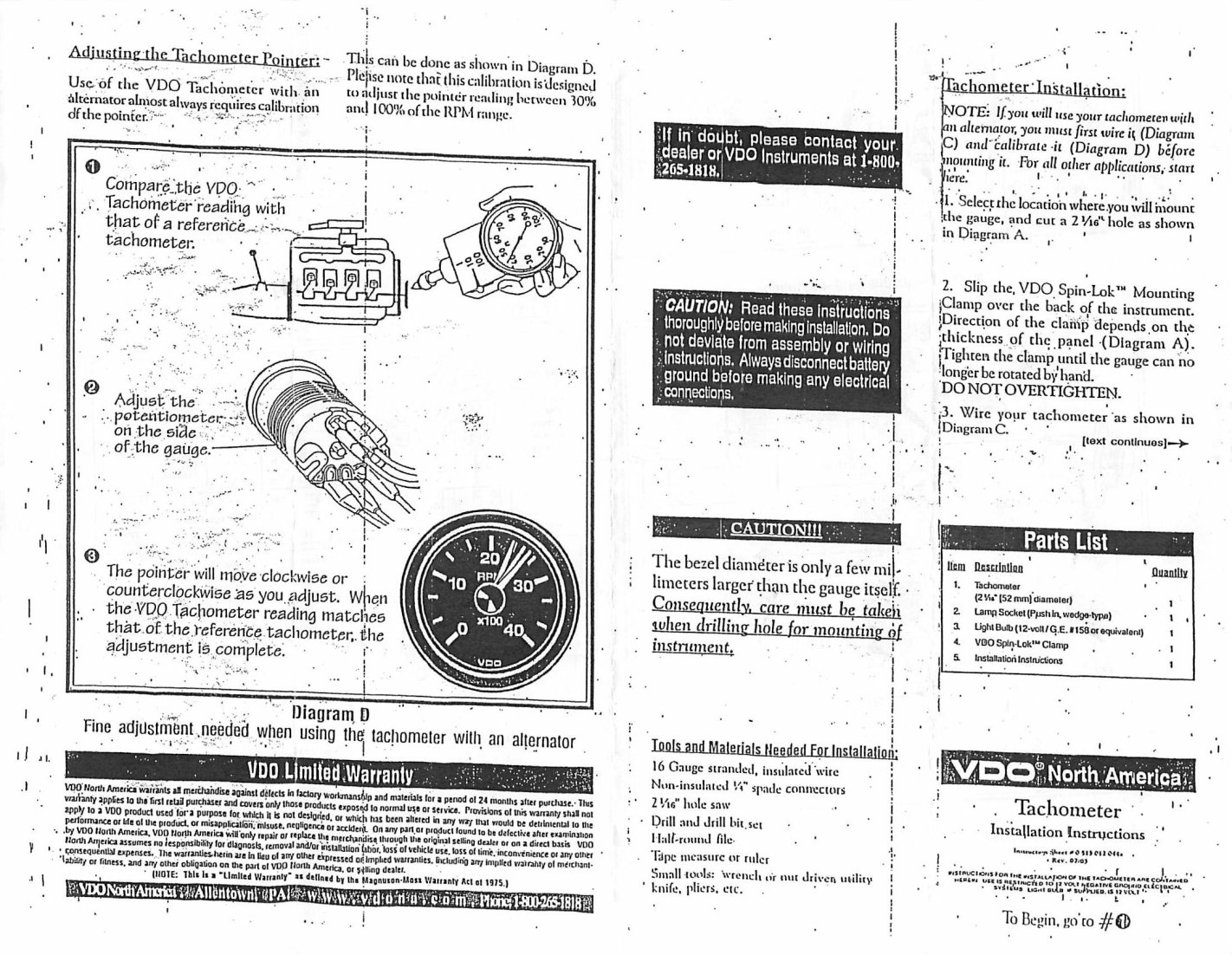 shown Diagram C. may mount tachometer an optional VDO mounting bracket nuts. I. Mounting Tachometer 1. Prepare insulated ¼" spade terminals use the tachometer. sure wires long to reach necessary positive negative terminals any wires the sensor. 2. Connect wire .
 SHIELDED CABLE #1 Posi-Lock Connector TACH SIGNAL SHIELDED CABLE #2 Posi-Lock Connector + TACH - POWER Diagram Wiring the Tachometer the Ignition Coil MSD-6 on Page 4, the text in Diagram G. I. Street Eliminator Operation CONNECTING THE IGNITION COIL MSD-6 tachometer designed those individuals .
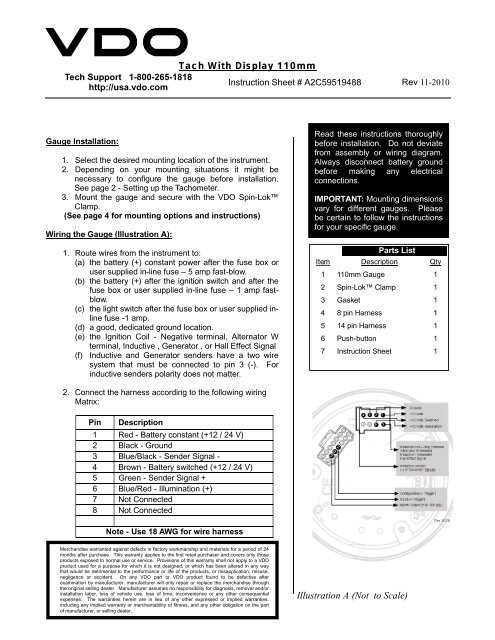 check wiring, referring the wiring description Diagram C. d) location the signal source (alternator, coil other ignition signal source). 2. Connect wiring the tachometer terminals shown Diagram C. Configuring T achometer: your VDO Tachometer func-tion properly your engine, will
 TheSambacom :: VDO Tachometer Instructions
![[DIAGRAM] Vdo Tachometer Wiring Diagram Diesel - MYDIAGRAMONLINE [DIAGRAM] Vdo Tachometer Wiring Diagram Diesel - MYDIAGRAMONLINE](https://www.thesamba.com/vw/gallery/pix/590656.jpg) [DIAGRAM] Vdo Tachometer Wiring Diagram Diesel - MYDIAGRAMONLINE
[DIAGRAM] Vdo Tachometer Wiring Diagram Diesel - MYDIAGRAMONLINE
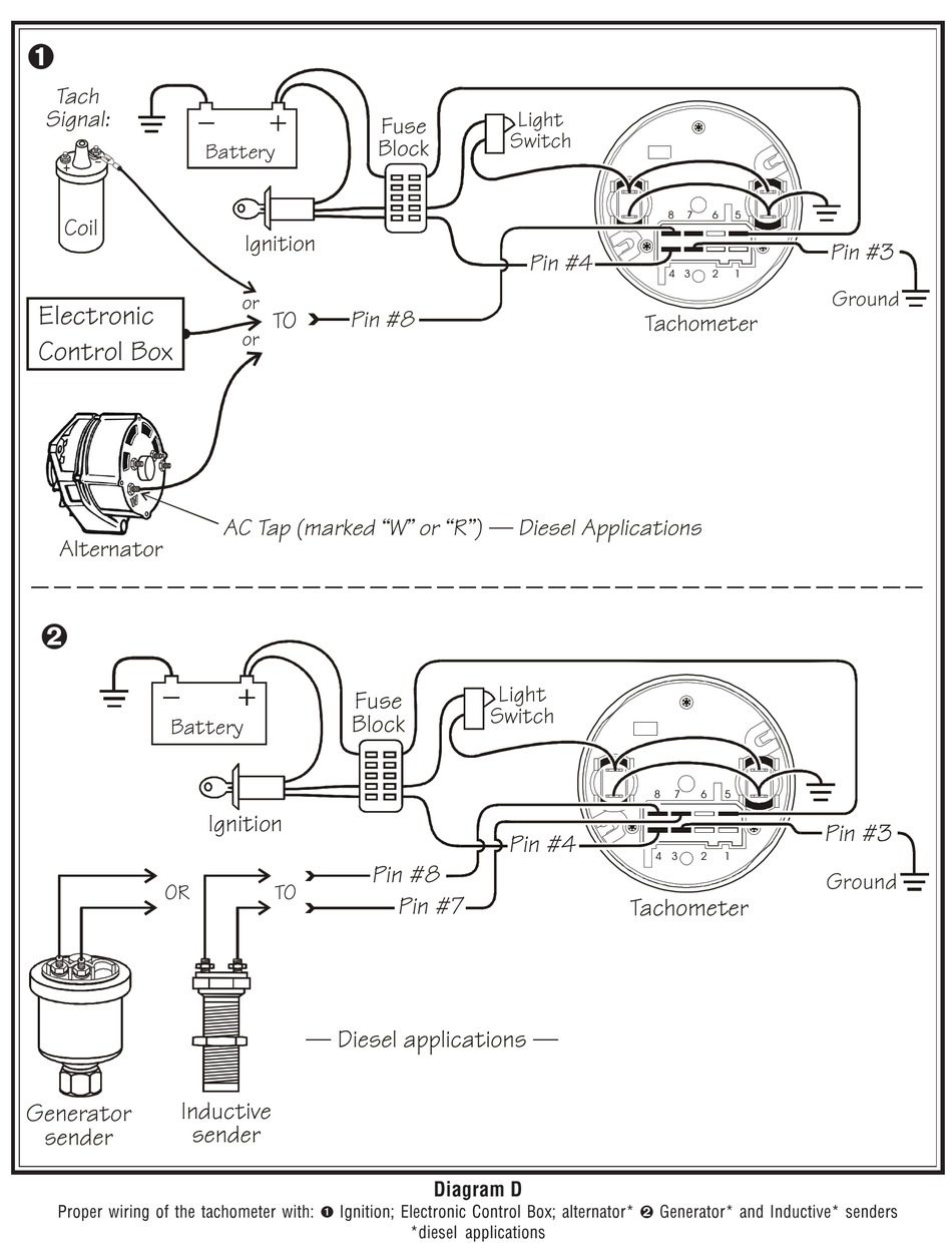 Vdo Tachometer Wiring Diagram
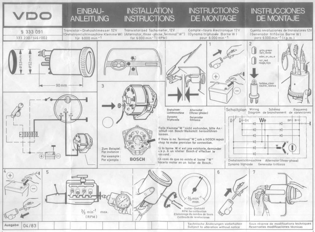 Vdo Tachometer Wiring Diagram
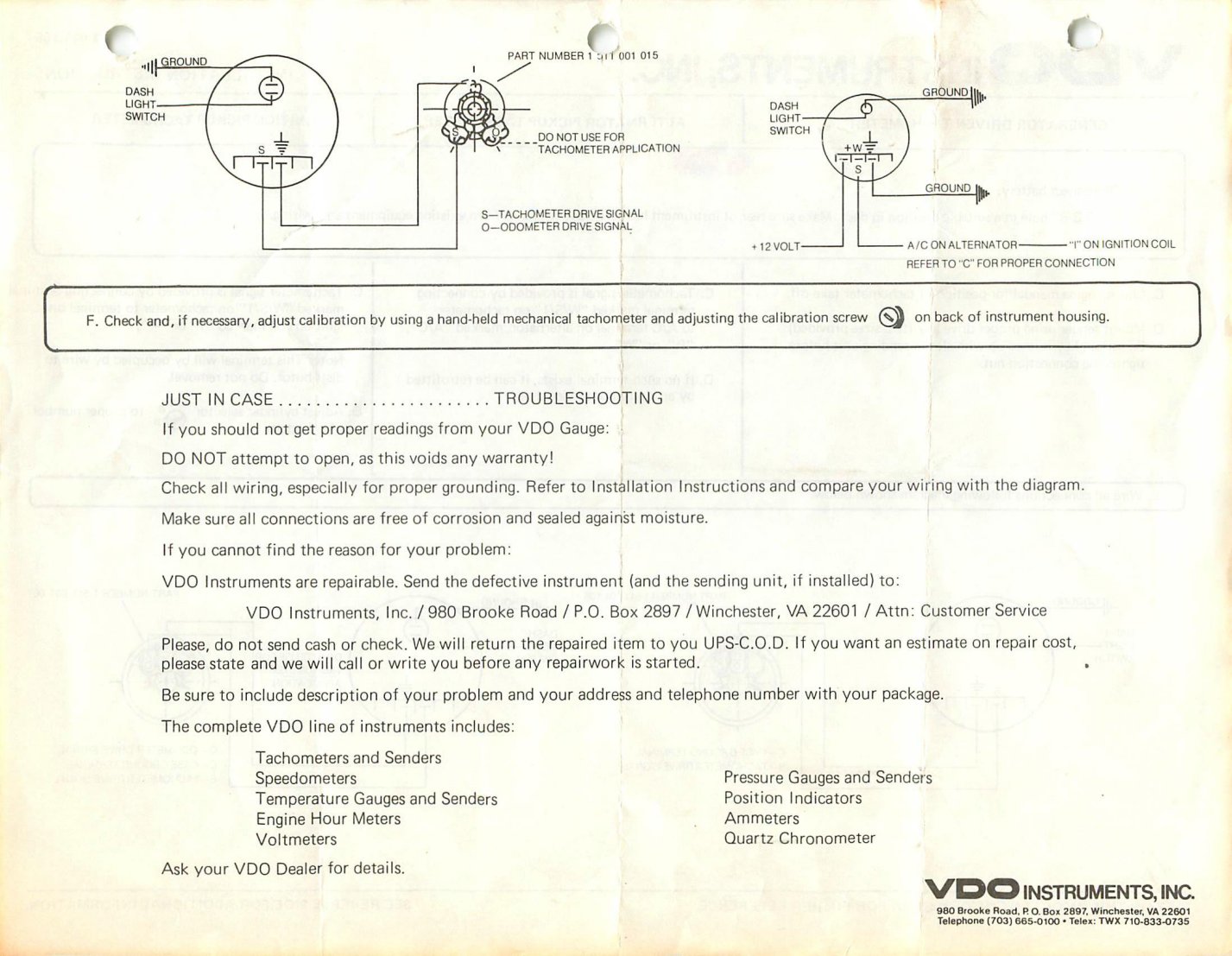 Vdo Tach Wiring Instructions Diagram
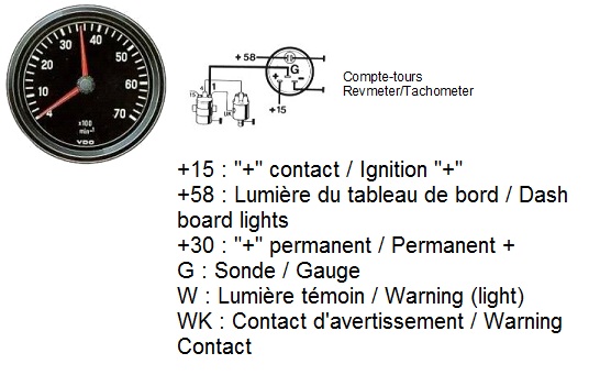 Wiring Diagram For Vdo Tachometer Database
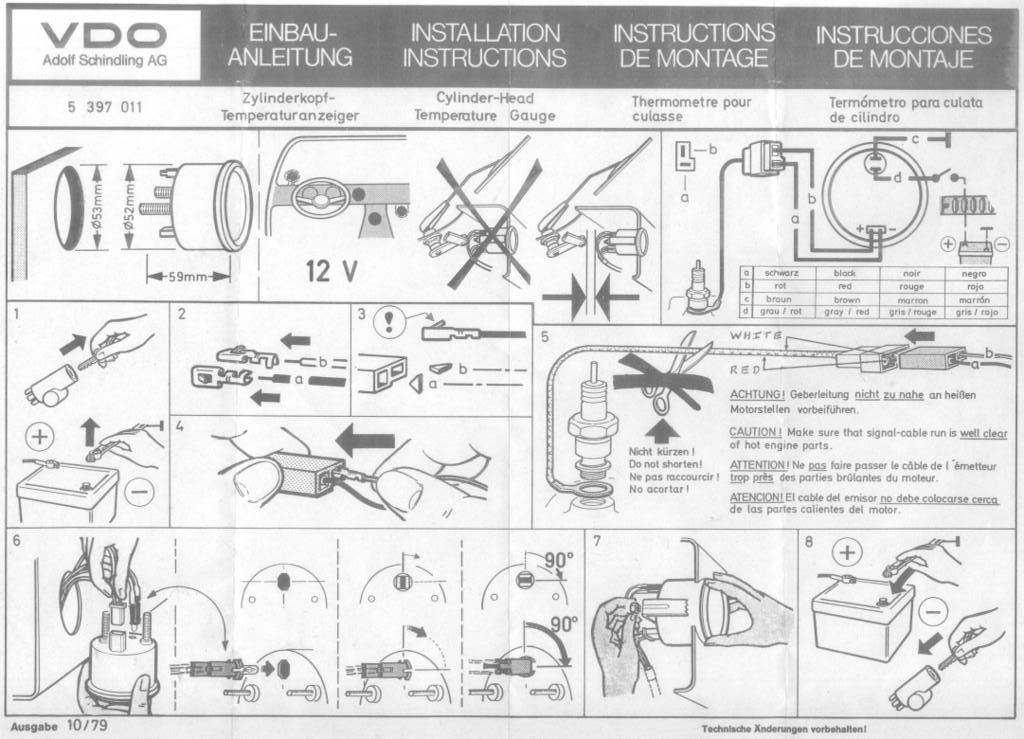 Vdo Tachometer Wiring Diagram 4000
 Vdo Tachometer Wiring Diagram - Crafts Pass
 Vw Vdo Tach Wiring Diagram
 Vdo Wiring Diagrams For Vw
 Vdo Tachometer Wiring
