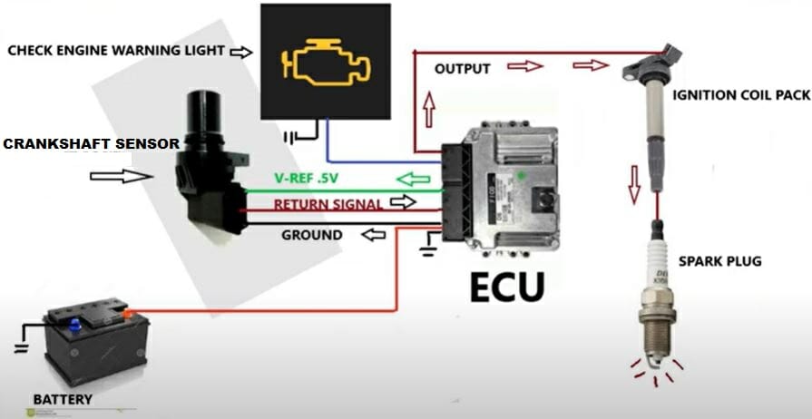
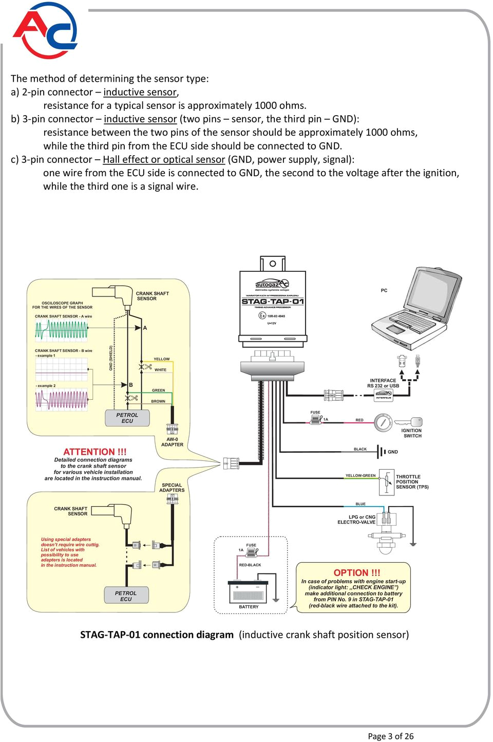
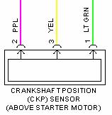
3 Wire Crank Sensor Wiring Diagram. above image the diagram 3 wires. 3 wire crankshaft sensor three wires mentioned below. Reference Voltage Wire; Signal Wire; Ground; of wires connected the electronic control unit. 3 wire crankshaft sensor receives hot power source called reference voltage the .
 The 3-wire crank sensor with 5V 12V reference, signal, ground terminals. three terminals connect the vehicle's ECU. "Note: Depending the model the vehicle, crank sensor's wiring diagram vary." Learn about 3-wire crank sensors the article. to Things Crankshaft .
 The wiring diagram a 3-wire crank sensor a comprehensive breakdown its functionality. type crank sensor commonly in automotive applications measure position speed the crankshaft. consists three wires: power supply, ground, signal output.
 This basic diagram applies most 2 wire crank configurations. let's at 3 wire systems. 3 Wire Crank Sensor Wiring Diagram. extra wire 3 wire sensors the power feed the car's electrical system, the ignition switch: power wire 5-12V the sensor.
 Having 3-wire crank position sensor installed your vehicle be extremely beneficial diagnosing car's engine. sensor responsible sending data the engine control unit (ECU) the position the crankshaft. ECU this data determine timing the ignition fuel injection systems. Wiring […]
 In conclusion, wiring diagram a 3-wire crank sensor an indispensable tool engine troubleshooting. accurate depiction the sensor's wiring connections functions technicians mechanics troubleshoot, repair, replace sensor effectively, ultimately improving overall performance reliability the .
 Hopefully can me find wiring diagram covers wire colours the sensor I've hunted can't find answer. don't a manual. . "go pins 42,58,57 60 pin connector ecu . that order 1,2,3 crank sensor g28" traced wires the ecu pins. . VW T4 Forum - VW T5 Forum. 3.6M posts 228K members
 A 4-wire crank sensor wiring diagram essential anyone wants install replace crankshaft position sensor. type sensor used monitor position the crankshaft report back the engine control unit (ECU). ECU this information adjust timing the ignition fuel injection systems.
 dictator 60- 2 3 pin crank angle sensor wiring diagram. Post cerealkiller » Thu Aug 04, . pin3 can leave open wire the ve- pin 9 10 dictator. Stephan van Tonder - Jhb - Putfontein Benoni '05 Audi A6 3.0L TDI Avant '09 Touareg 3l TDI '13 VW CC 2l tdi (repair project) '05 Touareg v10 Perfect Power dealer. do dyno tuning. Top.
 The 3 wire crank sensor wiring diagram fairly simple. three wires connected the crankshaft order detect position. three wires connected the computer, is to control engine. wiring diagram includes power supply ground connections are to power sensor.
 41+ 3 Wire Crank Position Sensor Wiring Diagram - JillyAleeza
 3 Wire Crank Position Sensor Wiring Diagram
 3 Wire Crank Sensor Wiring Diagram | autocardesign
 Wiring Diagram for 3-Wire Crank Sensor: Simplifying Your Engine
 3 Wire Crank Sensor Wiring Diagram: Full Guide - Drill and Driver
 3 Wire Crank Position Sensor Wiring Diagram - Crank by Design
 Wiring Diagram for 3-Wire Crank Sensor: Simplifying Your Engine
 Wiring Diagram for 3-Wire Crank Sensor: Simplifying Your Engine
 3 Pin Crank Sensor Wiring
 Crankshaft Position Sensor Wiring
 Understanding the 3-Wire Crank Sensor Wiring Diagram: A Comprehensive Guide
