Overall, understanding properly wiring 3 Phase Submersible Water Pump Wiring Diagrams essential maintain safety efficacy any pump. following steps, system owners operators ensure pumps run optimally without risks. Control Panel Submersible Molock Pumpset Pump Starter Circuit


 In diagram, showed 3 Pole MCCB breaker, magnetic contactor, thermal overload protection relay, normally open, normally close push button switches. 3-phase submersible pump motor electric wiring connection. will the complete guide controlling three-phase submersible pump motor a magnetic contactor.
 st4/st6 series submersible pumps• operation parts manual — rev. #1 (11/12/13) — page 27 ConTrol box wiring Diagram (Cb1456/C b1463) L1 460 VAC THREE PHASE WIRING EXTERNAL 3-PHASE CONNECTIONS (460 VAC) POWER SOURCE CIRCUIT BREAKER RED WHITE BLACK L1 L2 L3 GREEN GROUND ON INDICATOR LAMP A2 A1 43 2 3 4 1 STOP FLOAT SWITCH START FLOAT .
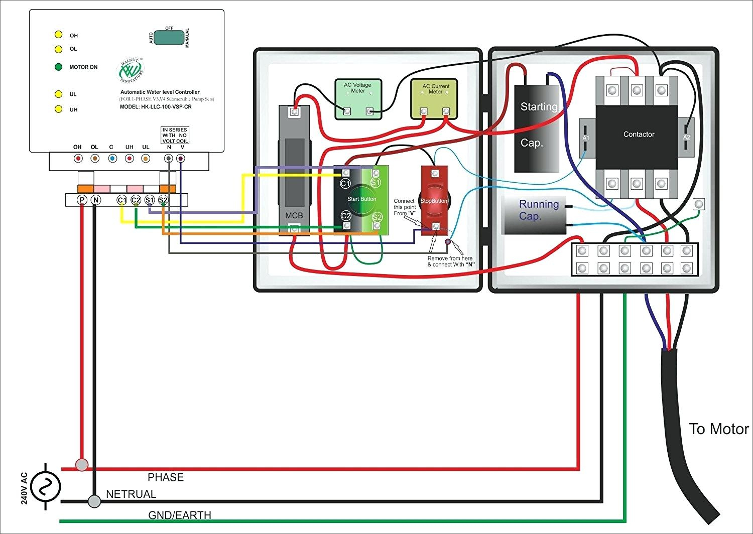
 The three-phase submersible pump control panel wiring diagram a detailed illustration how control panel wired to submersible pump the external power source. It's essential part the system, it's main of controlling pump preventing kind malfunction occurring.
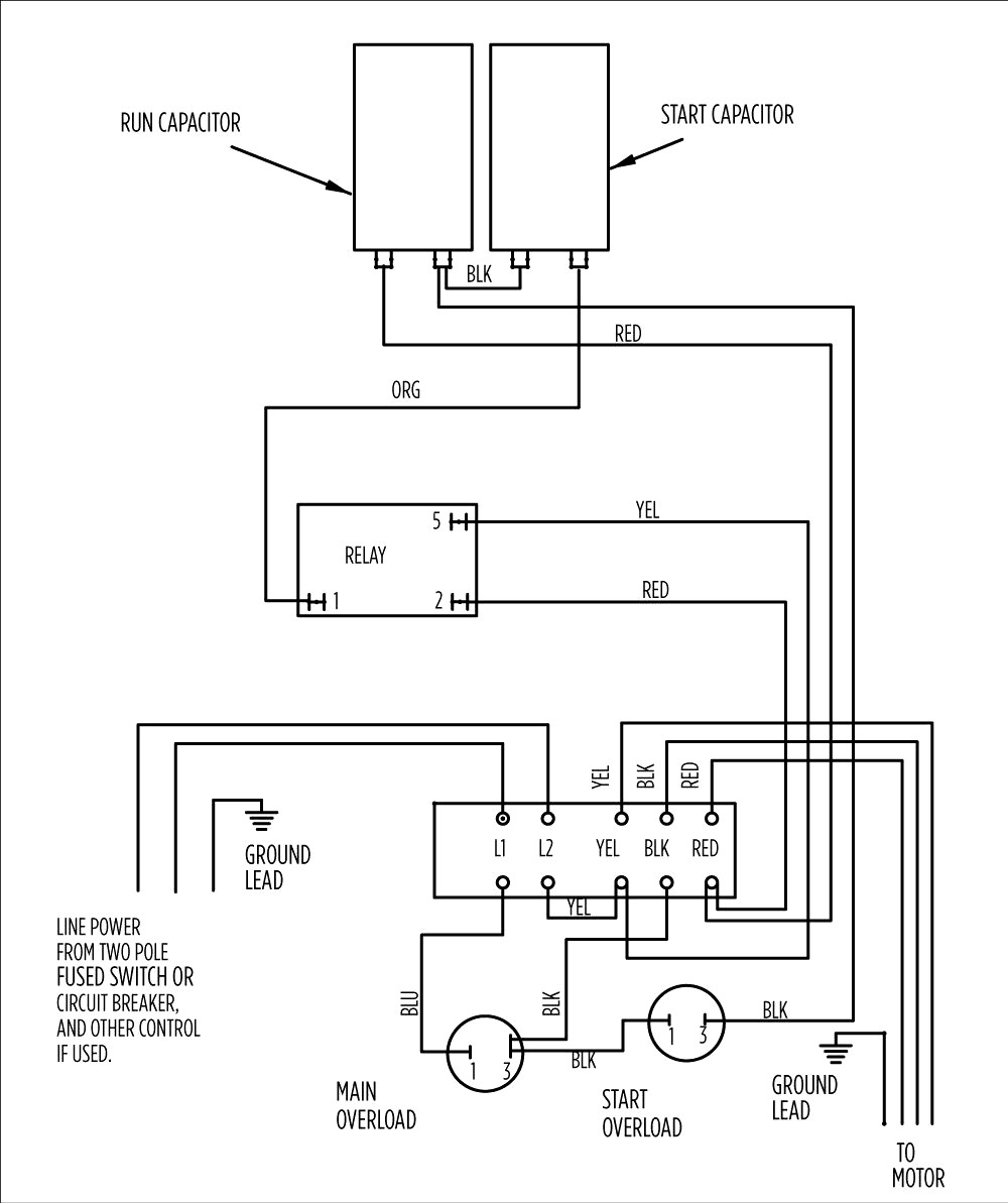
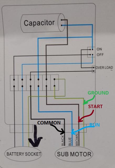
 Important components submersible pump wiring diagram: Pump Motor: is main component drives pump. is a hermetically sealed motor is designed work underwater. Control Box: control box regulates operation the submersible pump. contains electrical components, as capacitors .
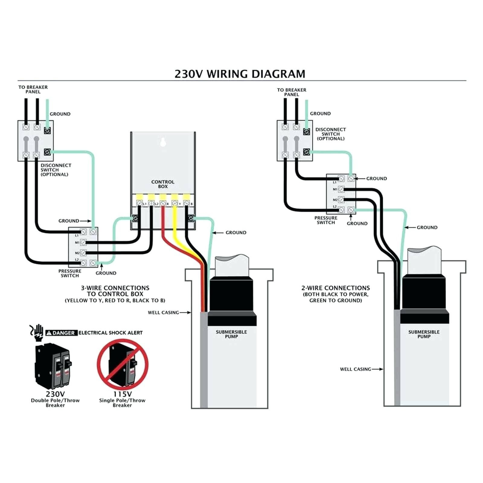
 Well pump wiring diagrams, 3-wire, 4-wire, . Typical 3 4-wire submersible pump control box wiring diagram. 4-wire pump wiring connections typical a single-phase submersible pump. GREEN = ground; BLUE = run - will one the Line power wires;
 The connection be with submersible pump motor. hope fully automatic water level controller wiring diagram a three-phase motor a magnetic contactor helped you. if needed automatic water level controller wiring a diagram a submersible pump motor with direct online starter.
 Three-phase Submersible Pump Wiring Diagram a direct online starter First, the 3 phase submersible pump wiring diagram after that,we explain step the connection diagram. the figure, have shown L1, L2, L3 N-line input power red, yellow, blue, black. them, red, yellow, blue .
![[DIAGRAM] Wiring Diagram Panel Pompa Submersible 3 Phase - MYDIAGRAMONLINE [DIAGRAM] Wiring Diagram Panel Pompa Submersible 3 Phase - MYDIAGRAMONLINE](https://inspectapedia.com/water/Submersible-well-pump-wire-Tests-Goulds.jpg) [DIAGRAM] Wiring Diagram Panel Pompa Submersible 3 Phase - MYDIAGRAMONLINE
[DIAGRAM] Wiring Diagram Panel Pompa Submersible 3 Phase - MYDIAGRAMONLINE
 3 phase Submersible pump starter connection | Part 1 - YouTube
 3 Wire Submersible Well Pump Wiring Diagram - Paintal
 3 phase submersible pump wiring diagram pdf - Wiring Diagram and Schematics
 3 Phase Submersible Pump Wiring Diagram
 3 Wire Submersible Pump Wiring Diagram


 How To Make Submersible Pump Control Box Connection Wiring Diagram
 Submersible Pump Wiring Connection
 Submersible pump wiring diagram - Earth Bondhon