In typical three-phase rotary switch wiring diagram, will find combination colors represent different poles wires. colors help figure which poles to connected together, where attach ground wire. Additionally, pole also its terminals, allowing to break .
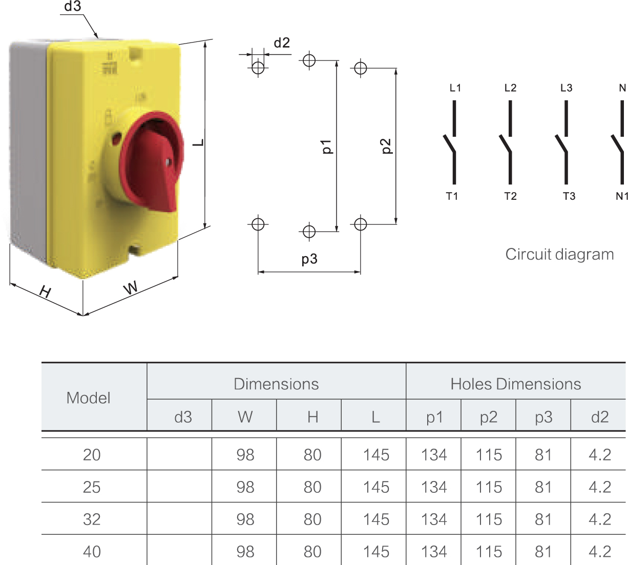
 next. images the show wiring connections both supply load. example, L1 connects switch terminal 1 U1 T1 connects terminal 2. Connection Details information presented either switch chart or switch chart connection diagrams appropriate. 0 13575311911 246684121011 0 XX .
 It three voltages be adjusted the power be divided two more parts. Depending the type three-phase switch, may either rotary slide switch. Components a 3-Phase Rotary Wiring Diagram 3 phase rotary switch wiring diagram made of components, of serves important .
 (3- phase) Machinery (3- phase) Machinery 230 volt (three- phase panel) On NOTE: wiring be by licensed electrician. load voltages require transformer the three-phase panel. (3- phase) Machinery Wiring Diagram motor loads total to 3 times maximum converter rated current.
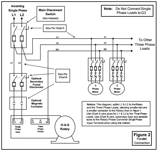
 Connect single-phase power the terminals marked L1 L2 the main disconnect switch use diagrams different wiring ideas, this one: have wiring diagrams this article: " Rotary Phase Converter Wiring Diagram ". is quick infographic (or short summary wiring) your reference .
 The wiring diagram a rotary 3-phase converter typically consists three main components: input power supply, rotary converter, the output power supply. input power supply usually single-phase provides initial power start rotary converter. can from utility grid an alternative power source .
 All Pro Line 3 phase rotary switch wiring phase converters include Allen Wrenches needed installation. of T1, T2, T3 power distribution blocks double-locks. idler generator motor attaches one set holes the power distribution block.
 The goes your wire gauge. company provided with motor, give the details. Step 3. Connect single-phase power the terminals marked L1 L2 the main disconnect switch use diagrams different wiring ideas, the shown below. Step 4.
 A three-phase rotary converter wiring diagram outlines electrical connections needed wire components a power system. Understanding three-phase rotary converter wiring diagram an important step any electrician technician responsible wiring systems. guide provide overview what's needed .
 A rotary changeover switch wiring diagram includes: 1. Rotary Switch. switch indicated an arrow a circle the central component. connects number terminals different areas. 2. Terminals . Wire connections electrical flow made by switch's identified terminals. 3. Connections Wires
 3 Position Rotary Switch Wiring Diagram | Prs guitar, Guitar, Wire
 3 PHASE MANUAL ROTARY SWITCH CONNECTION STEP BY STEP #controlpanel #
 3 phase DB wiring with rotary switch connections in தமிழ் - YouTube
![Single Line Diagram Of Three Phase Motor [diagram] Wiring Di Single Line Diagram Of Three Phase Motor [diagram] Wiring Di](/img/placeholder.svg)
 3 Phase Motor Connection with Rotary Switch @ElectricalTechnician - YouTube
 3 Phase Rotary Switch Diagram - Easy Wiring
 Rotary Switch Wiring Diagram
![[DIAGRAM] Hoa Switch Wiring Diagram 3 Phase Motor Control - MYDIAGRAM [DIAGRAM] Hoa Switch Wiring Diagram 3 Phase Motor Control - MYDIAGRAM](https://i.ytimg.com/vi/wgB2GQ6O5W4/maxresdefault.jpg) [DIAGRAM] Hoa Switch Wiring Diagram 3 Phase Motor Control - MYDIAGRAM
[DIAGRAM] Hoa Switch Wiring Diagram 3 Phase Motor Control - MYDIAGRAM
 Three Phase Rotary Switch Wiring Diagram - Circuit Diagram
 3 phase rotary switch connection | Electrical ac switch | selector
 3 Phase Auto Switch Circuit Diagram
