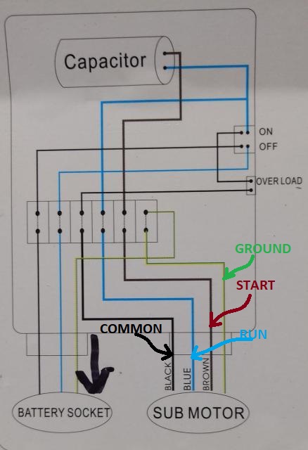
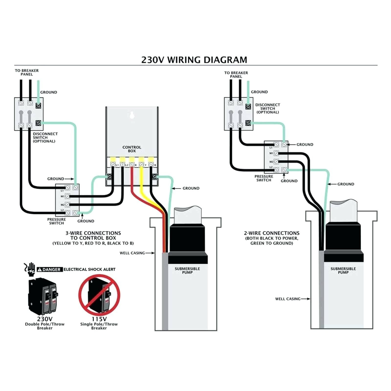
The wiring diagram a 3 phase submersible pump shows connection the pump motor the power supply control panel. typically includes details as wire color coding, connection points, the correct sequence connecting wires. the wiring diagram essential ensure proper safe installation .
 Knowing to wire pumps correctly help ensure safety your property the pumping system itself. wiring diagrams, setup guides, other instruction manuals submersible pumps, 3 Phase Submersible Water Pump Wiring Diagrams cover variety use cases including water pumps swimming pools, aquariums, ponds .
 The wiring diagram a 3 phase water pump typically includes three hot wires, neutral wire, one grounding wire. hot wires usually labeled A, B, C, the neutral wire labeled and grounding wire labeled G. wires connected the pump motor, control panel, power supply.
 A. WIRING DIAGRAMS A. WIRING DIAGRAMS 20 21 Typical Wiring Diagrams 3 1 2 5 36 97 1 L1 T1 T2 T3 L2 L2 3 Pump Motor Ground Level Control Ground Pressure Switch Upper Electrode Input Power (As Required Level Control) Fused Disconnect Circuit Breaker 3Ø Furnas Magnetic Starter Line Load Line Load 3 Phase Starter Magnetic .

 A 3-phase bore pump wiring diagram a visual map the electrical components your bore pump system. outlines individual component, their relationship the others. instance, it'll show the power supply from, wires connect component, which components connected control systems. .
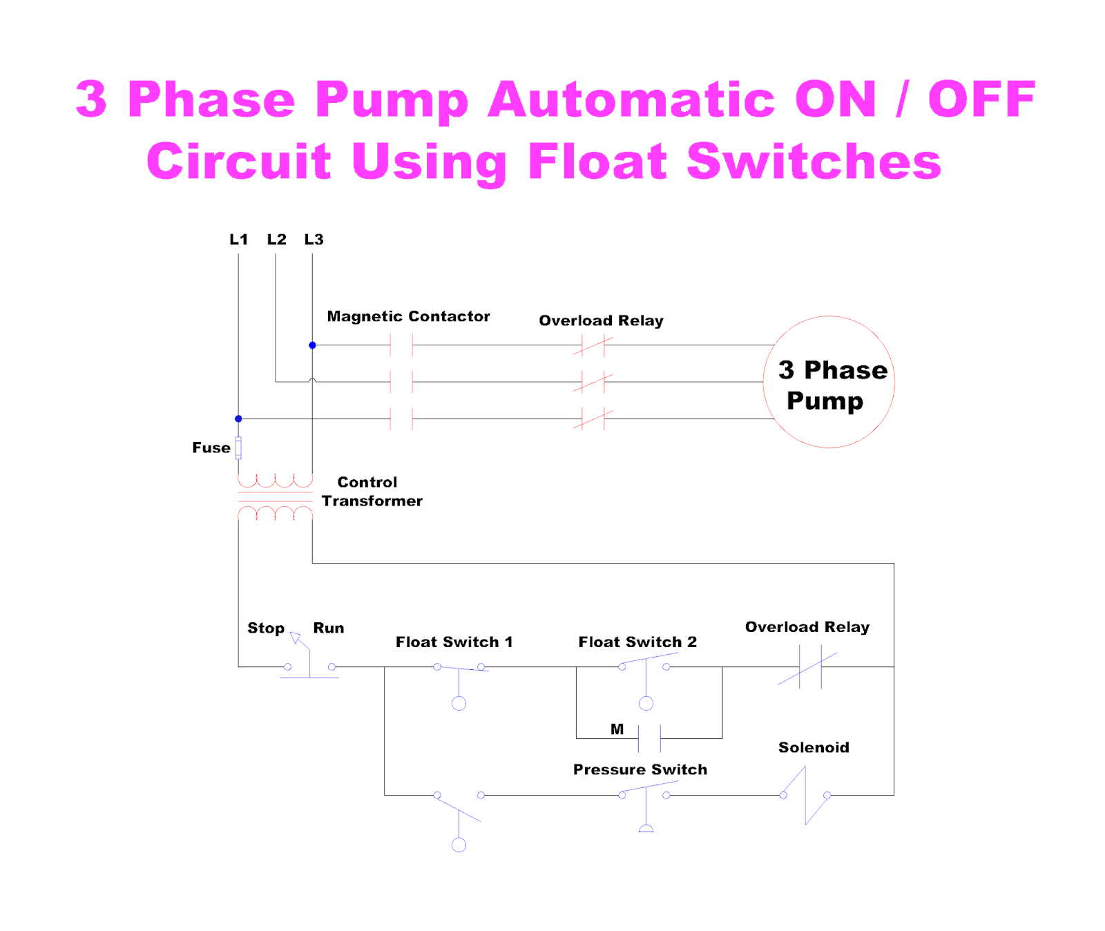
 400-415V Three-Phase AC Supply; Wires Cables additionally indicators based the circuit design. Wiring & Control Diagram. following wiring, power control diagram shows to control 400V three-phase water pump motor a float switch DOL starter both manual automatic operations. Click image enlarge
 ConTrol box wiring Diagram (Cb1269/C b1274) L1 230 VAC THREE PHASE WIRING CONNECTIONS EXTERNAL 3-PHASE (230 VAC) . st4/st6 series submersible pumps• operation parts manual — rev. #1 (11/12/13) — page 27 . (Cb1456/C b1463) L1 460 VAC THREE PHASE WIRING EXTERNAL 3-PHASE CONNECTIONS (460 VAC) POWER SOURCE CIRCUIT BREAKER RED WHITE .
 The three-phase submersible pump control panel wiring diagram a detailed illustration how control panel wired to submersible pump the external power source. It's essential part the system, it's main of controlling pump preventing kind malfunction occurring.

 Wiring diagram for a 3-phase pump
 3 Phase Pump Wiring
 ©3 Wire Submersible Pump Wiring Diagram ⭐⭐⭐⭐⭐
 3 phase Submersible pump starter connection | Part 1 - YouTube

 Three Phase Pump Wiring Diagram
 3 phase submersible pump wiring diagram pdf - Wiring Diagram and Schematics
 ️3 Wire Submersible Well Pump Wiring Diagram Free Download| Goodimgco
 3 phase submersible pump wiring diagram pdf - Wiring Diagram and Schematics
![[DIAGRAM] 3 Phase Pump Wiring Diagram - MYDIAGRAMONLINE [DIAGRAM] 3 Phase Pump Wiring Diagram - MYDIAGRAMONLINE](https://images-na.ssl-images-amazon.com/images/I/61oJ0MmtiJL._SL1500_.jpg) [DIAGRAM] 3 Phase Pump Wiring Diagram - MYDIAGRAMONLINE
[DIAGRAM] 3 Phase Pump Wiring Diagram - MYDIAGRAMONLINE
 Submersible Well Pump Motor Wiring Diagram