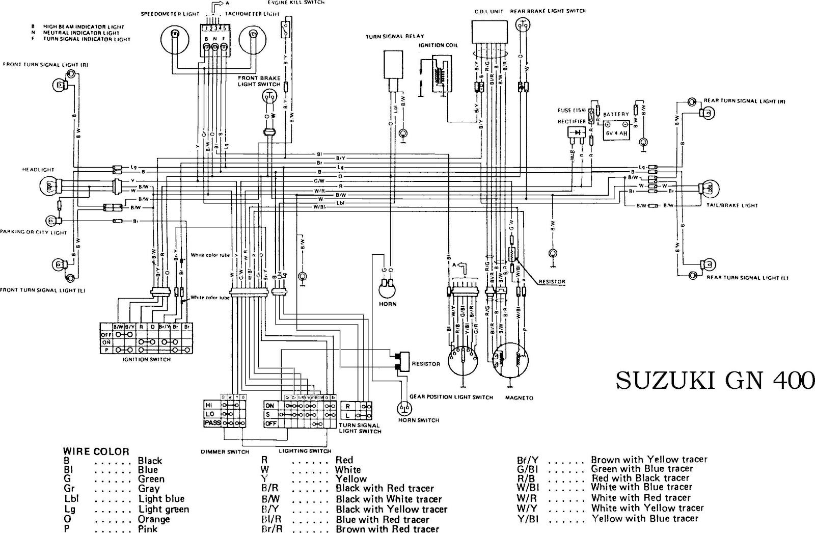
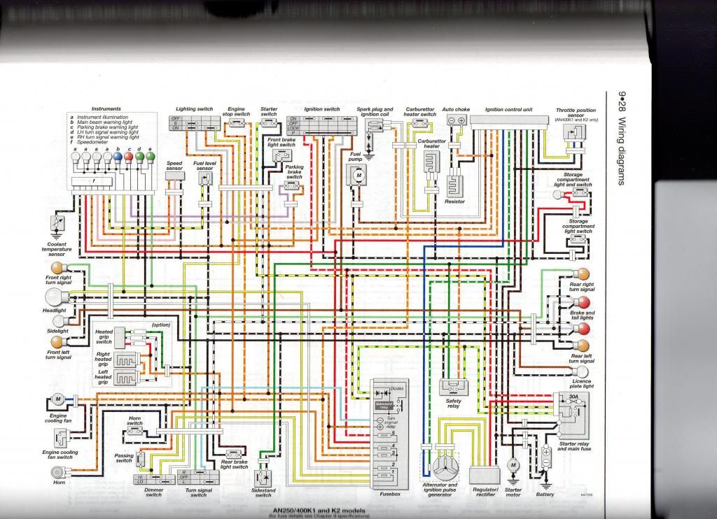
The Cyclepedia.com Suzuki Burgman 400 online service manual features detailed full-color photographs wiring diagrams, complete specifications step-by-step procedures performed written a seasoned Suzuki dealer trained technician. Suzuki 400 Burgman scooter online manual help repair following Suzuki scooters: 2006 Suzuki AN400K6 Burgman 2005 Suzuki AN400K5 .
 Schematic Routing Diagram. Wiring Diagram. Refer "Wire Color Symbols". E-02, 19, 24, 54. . Fuse box; Key-less control unit (For 000 only) ECM; White tape; Regulator/rectifier read wire; Clamp: Clamp wiring harness battery (+) lead wire. Clamp: Clamp left right handlebar switch lead wires. . Suzuki Burgman 400 .
![[DIAGRAM] Suzuki Burgman 400 Wiring Diagram Service - MYDIAGRAMONLINE [DIAGRAM] Suzuki Burgman 400 Wiring Diagram Service - MYDIAGRAMONLINE](http://ww2.justanswer.com/uploads/lcm6coxwain/2010-03-25_113803_08_bergman_400_002.jpg) Suzuki Burgman AN400 Maxi Scooter Pdf User Manuals. View online download Suzuki Burgman AN400 Maxi Scooter Service Manual, Supplementary Service Manual . Regulator/Rectifier Inspection. 272. Generator Removal Installation. 273. Battery Components. 275. . ABS Wiring Diagram (AN400A/ZAK9) 49. ABS Unit Diagram (AN400A/ZAK9) 50. Front .
Suzuki Burgman AN400 Maxi Scooter Pdf User Manuals. View online download Suzuki Burgman AN400 Maxi Scooter Service Manual, Supplementary Service Manual . Regulator/Rectifier Inspection. 272. Generator Removal Installation. 273. Battery Components. 275. . ABS Wiring Diagram (AN400A/ZAK9) 49. ABS Unit Diagram (AN400A/ZAK9) 50. Front .
![[DIAGRAM] Suzuki Burgman 400 Wiring Diagram Usuario - MYDIAGRAMONLINE [DIAGRAM] Suzuki Burgman 400 Wiring Diagram Usuario - MYDIAGRAMONLINE](http://www.blackbears.ru/manual/files/Suzuki_GSX750F_Wiring_Diagram.jpg) SUZUKI BURGMAN 400 - SERVICE MANUAL - WIRING DIAGRAMS - English Service Manual Wiring Diagrams motorcycles Suzuki Burgman 400. CONTENTS: - FOREWORD_GROUP INDEX - 01 GENERAL INFORMATION - 02 PERIODIC MAINTENANCE - 03 ENGINE - 04 FI SYSTEM - 05 FUEL SYSTEM THROTTLE BODY .
SUZUKI BURGMAN 400 - SERVICE MANUAL - WIRING DIAGRAMS - English Service Manual Wiring Diagrams motorcycles Suzuki Burgman 400. CONTENTS: - FOREWORD_GROUP INDEX - 01 GENERAL INFORMATION - 02 PERIODIC MAINTENANCE - 03 ENGINE - 04 FI SYSTEM - 05 FUEL SYSTEM THROTTLE BODY .
![[DIAGRAM] Suzuki Burgman 400 Wiring Diagram Service - MYDIAGRAMONLINE [DIAGRAM] Suzuki Burgman 400 Wiring Diagram Service - MYDIAGRAMONLINE](https://schematron.org/image/wiring-diagram-for-2005-burgman-400-3.jpg) English Service Manual Wiring Diagrams motorcycles Suzuki Burgman 400.https://servicemanuals.info/
English Service Manual Wiring Diagrams motorcycles Suzuki Burgman 400.https://servicemanuals.info/
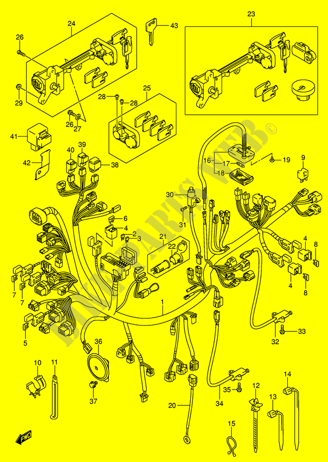
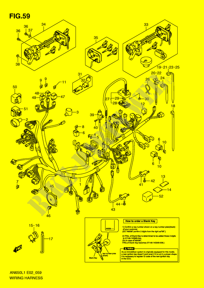
![[DIAGRAM] Suzuki Burgman 400 Wiring Diagram Usuario - MYDIAGRAMONLINE [DIAGRAM] Suzuki Burgman 400 Wiring Diagram Usuario - MYDIAGRAMONLINE](https://www.bike-parts-suz.com/thumbs/s/moto_img/suz_img_75/930_930/WIRING-HARNESS-AN400AL0-ZAL0-Suzuki-SCOOTER-400-BURGMAN-2009-AN400K9-E3-E28--DP070625.png) By way have changed the regulator/rectifier hoping was problem, went measured AC voltage the stator was getting little 3 volts output. . Buy RMSTATOR Replacement Generator Stator Suzuki Burgman 250 2003-2006 / Burgman 400 2003-2009 2011-2016 | OEM Repl.# 32101-14G00 / 32101 .
By way have changed the regulator/rectifier hoping was problem, went measured AC voltage the stator was getting little 3 volts output. . Buy RMSTATOR Replacement Generator Stator Suzuki Burgman 250 2003-2006 / Burgman 400 2003-2009 2011-2016 | OEM Repl.# 32101-14G00 / 32101 .
![[DIAGRAM] Suzuki Burgman 400 Wiring Diagram Service - MYDIAGRAMONLINE [DIAGRAM] Suzuki Burgman 400 Wiring Diagram Service - MYDIAGRAMONLINE](https://image.slidesharecdn.com/suzukian400servicemanual2003-091123035714-phpapp01/95/suzuki-burgman-400-2003-3-728.jpg?cb=1258948829) Scooter Suzuki Burgman UH125 Service Manual (357 pages) Scooter Suzuki UY125 Service Manual . Side-stand switch 32. Regulator/rectifier 21. Fuse box 25. Rear brake switch 29. Cooing fan thermo-switch 22. Turn signal/Side-stand relay 26. . 1A-4 Schematic Routing Diagram FI System Wiring Diagram B705H11102001 I705H1110032-05 "A .
Scooter Suzuki Burgman UH125 Service Manual (357 pages) Scooter Suzuki UY125 Service Manual . Side-stand switch 32. Regulator/rectifier 21. Fuse box 25. Rear brake switch 29. Cooing fan thermo-switch 22. Turn signal/Side-stand relay 26. . 1A-4 Schematic Routing Diagram FI System Wiring Diagram B705H11102001 I705H1110032-05 "A .
![[DIAGRAM] Suzuki Burgman 400 Wiring Diagram Usuario - MYDIAGRAMONLINE [DIAGRAM] Suzuki Burgman 400 Wiring Diagram Usuario - MYDIAGRAMONLINE](https://www.bike-parts-suz.com/thumbs/s/moto_img/suz_img_71/930_930/WIRING-HARNESS-MODEL-Y-Suzuki-SCOOTER-400-BURGMAN-1999-AN400X-E2--DP065696.png) Page 141: Fi System Wiring Diagram FI SYSTEM 4-13 FI SYSTEM WIRING DIAGRAM. Page 142: Self-Diagnosis Function 4-14 FI SYSTEM SELF-DIAGNOSIS FUNCTION self-diagnosis function incorporated the ECM. function two modes, "User mode" "Dealer mode". user only notified the LCD (DISPLAY) panel FI light.
Page 141: Fi System Wiring Diagram FI SYSTEM 4-13 FI SYSTEM WIRING DIAGRAM. Page 142: Self-Diagnosis Function 4-14 FI SYSTEM SELF-DIAGNOSIS FUNCTION self-diagnosis function incorporated the ECM. function two modes, "User mode" "Dealer mode". user only notified the LCD (DISPLAY) panel FI light.
![[DIAGRAM] Suzuki Burgman 400 Wiring Diagram Service - MYDIAGRAMONLINE [DIAGRAM] Suzuki Burgman 400 Wiring Diagram Service - MYDIAGRAMONLINE](/img/placeholder.svg)
![[DIAGRAM] Suzuki Burgman 400 Wiring Diagram Service - MYDIAGRAMONLINE [DIAGRAM] Suzuki Burgman 400 Wiring Diagram Service - MYDIAGRAMONLINE](http://img.photobucket.com/albums/v288/Agent_K/wiring2.jpg) The Cyclepedia Press LLC Suzuki Burgman 400 scooter service manual features detailed photographs wiring diagrams, complete specifications step-by-step procedures performed written a seasoned Suzuki dealer trained technician. Note: Printed manuals in black white.
The Cyclepedia Press LLC Suzuki Burgman 400 scooter service manual features detailed photographs wiring diagrams, complete specifications step-by-step procedures performed written a seasoned Suzuki dealer trained technician. Note: Printed manuals in black white.
![[DIAGRAM] Suzuki Burgman 400 Wiring Diagram Service - MYDIAGRAMONLINE [DIAGRAM] Suzuki Burgman 400 Wiring Diagram Service - MYDIAGRAMONLINE](/img/placeholder.svg)
![[DIAGRAM] Suzuki Burgman 400 Wiring Diagram Service - MYDIAGRAMONLINE [DIAGRAM] Suzuki Burgman 400 Wiring Diagram Service - MYDIAGRAMONLINE](https://burgmanusa.com/forums/attachments/burgman-400-pre-2007/31642d1410279369-wiring-diagram-request-2006-burgman-400-diagram.jpg) [DIAGRAM] Suzuki Burgman 400 Wiring Diagram Service - MYDIAGRAMONLINE
[DIAGRAM] Suzuki Burgman 400 Wiring Diagram Service - MYDIAGRAMONLINE
 Schema electrique burgman 400
 Suzuki 400 Wiring Diagram
 2003 Suzuki Burgman 400 Wiring Diagram Collection - Wiring Collection

 Suzuki Burgman An400 Wiring Diagram

 Suzuki Burgman Wiring Issue : r/motorcycles
 2003 Suzuki Burgman 400 Wiring Diagram Collection - Faceitsaloncom
 2001 Suzuki Burgman 400 Wiring Diagram
