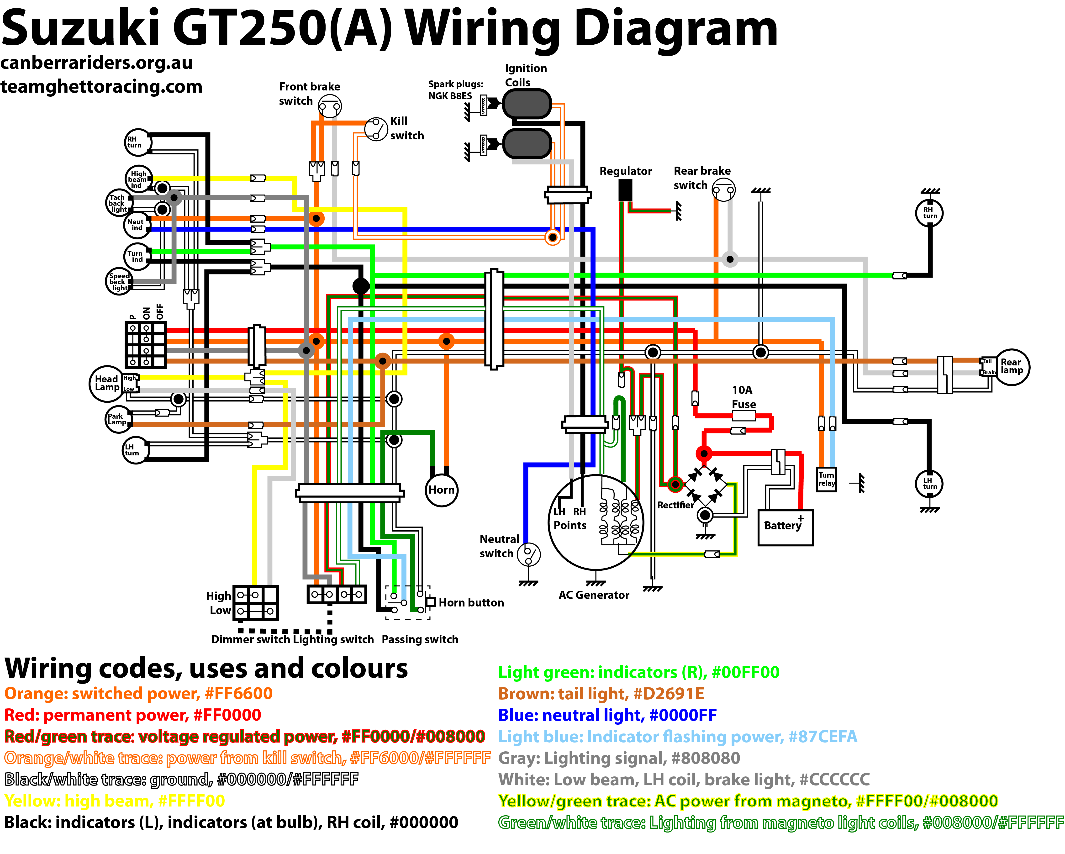
Wiring 1999 df 70 tach & hour meter 12-03-2016, 06:03 PM. Im wiring 1999 DF70 Tach Hour meter would to switch light red/green wire feeding gauge light bow light switch is 12V circuit is ok do? . SUZUKI WIRING DIAGRAM SHOWS GREY WIRE CONNECTED RED/GREEN WIRE {RETURNING POWER ECU} A .
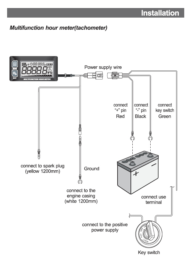
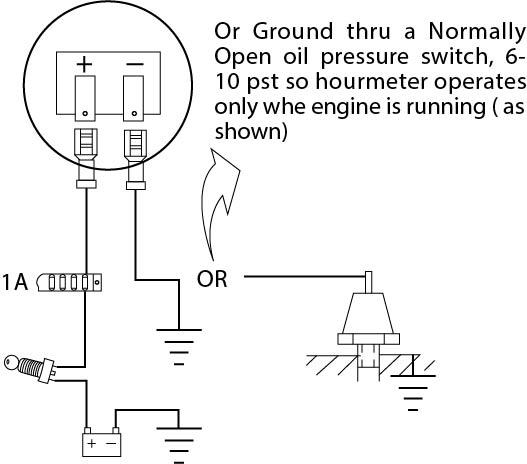
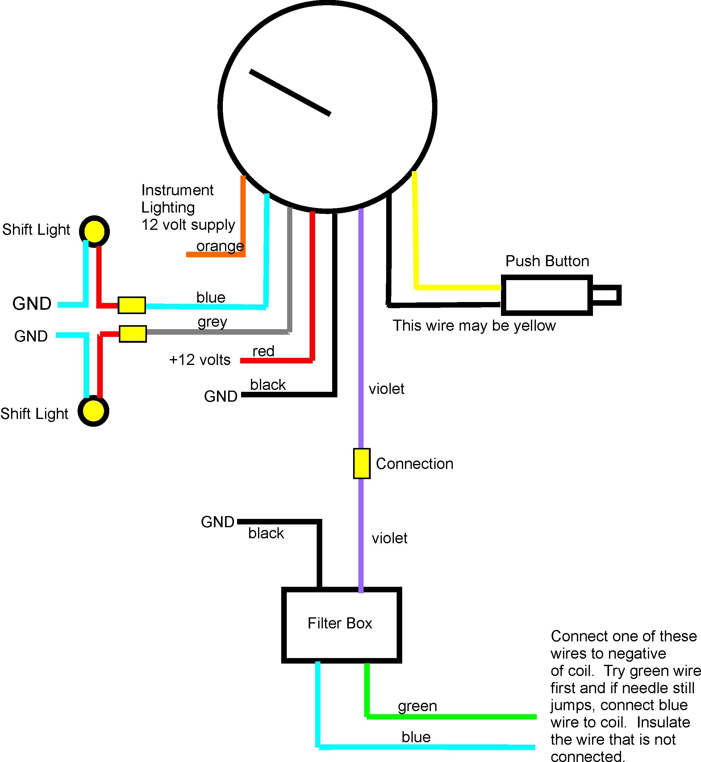 Re: to wire an hour meter? are of luck. hour meter a clock requires switdched 12 volts ground it run long the key on -- engine running not. the question -- do leave key on. cannot hook to coil that a pulsed signal.
 • Speed meter pickup tube 3 (3) Connect battery wire B the engine side. (4) Connect remote control harness to engine side, press fit connector the holder. NOTE: Moving parts located of throttle body, rods throt-tle cam always free contacting the remote control wire harness .
 Engine General Information Diagnosis: 1A-23 Self-Diagnostic Code "1 - 4" Cylinder Temp. Sensor Z9J0111104004 Wiring Diagram Lg/W I9J011110021-03 1. Cylinder temp. sensor Troubleshooting Step Action 1) the ignition switch "OFF", disconnect Cylinder to step 2. • "Lg/W" wire shorted Temp.
 Schematic Routing Diagram Wiring Diagram Z9J0114102004 Refer "Wire Color Symbols" Section 0A (Page 0A-2). . GND STOP BATT IG START BZ RESET REMOTE CONTROL BOX SUZUKI DN IGNITION SWITCH EMERGENCY STOP SWITCH LOCK PLATE RUN LOCK PLATE STOP BZ CAUTION BUZZER Lb Lg . METER TRIM METER TACHOMETER LED B B Gr
 Suzuki DF 70 Pdf User Manuals. View online download Suzuki DF 70 Service Manual. Sign Upload. Manuals; . Operating Hour Indication System. 79. Oil Change Reminder System. 80. Start-In-Gear Protection System. 82. . System Wiring Diagram. 218. Service Procedure. 219. Oil Level. 219. Air Bleeding. 219. Power Trim Tilt Unit. 220 .

 Suzuki Multi-function Gauge Installation Manual Post jimh » Mon Jun 14, 2021 8:14 pm you find link download PDF file the SUZUKI publication, Suzuki Multi-function Gauge Installation Manual:
 coded wire extension leads. 3. Cut 3-3/8" hole the dash mount tachometer the backclamp supplied. 4. Connect Grey wire the Harness connector marked (Ignition). 5. Connect Yellow wire the Harness connector marked (signal). 6. Connect Black wire the Harness connector marked (ground).
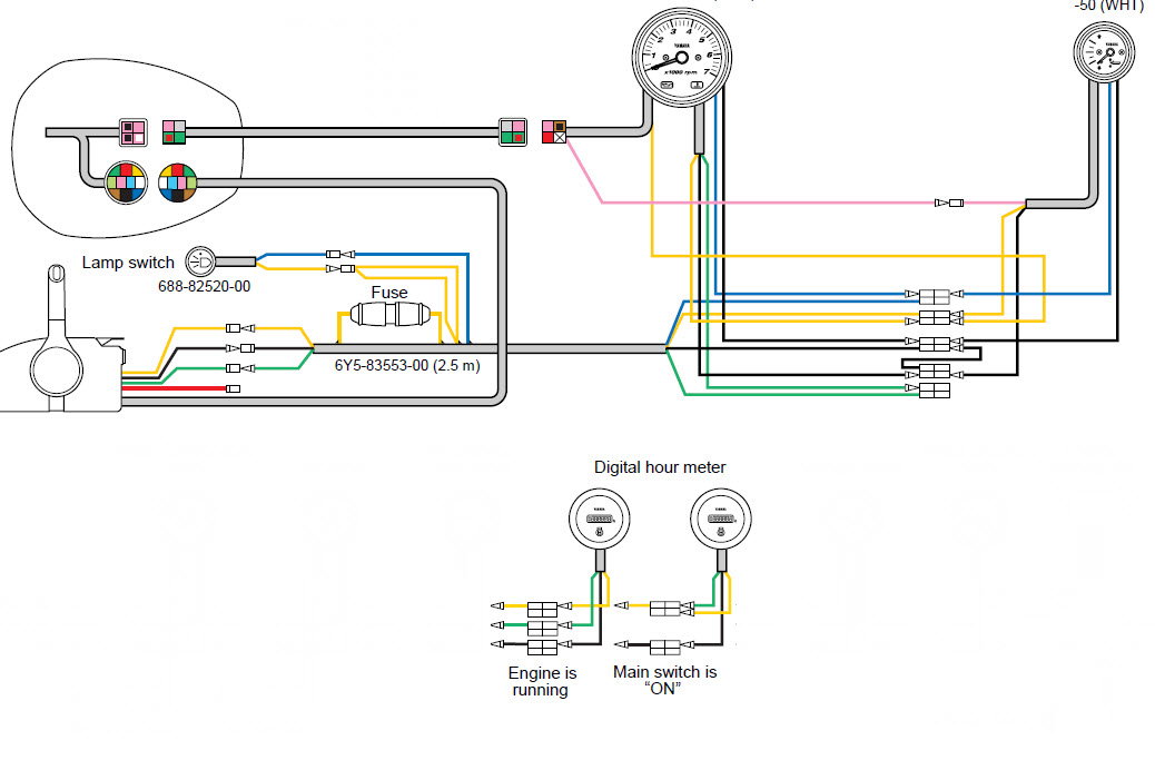 Understanding Basics Suzuki Outboard Tachometer Wiring. Suzuki outboard tachometers an essential component monitoring maintaining performance your boat's engine. devices provide accurate readings the engine's RPM (revolutions minute), allowing to optimize fuel efficiency identify potential issues.
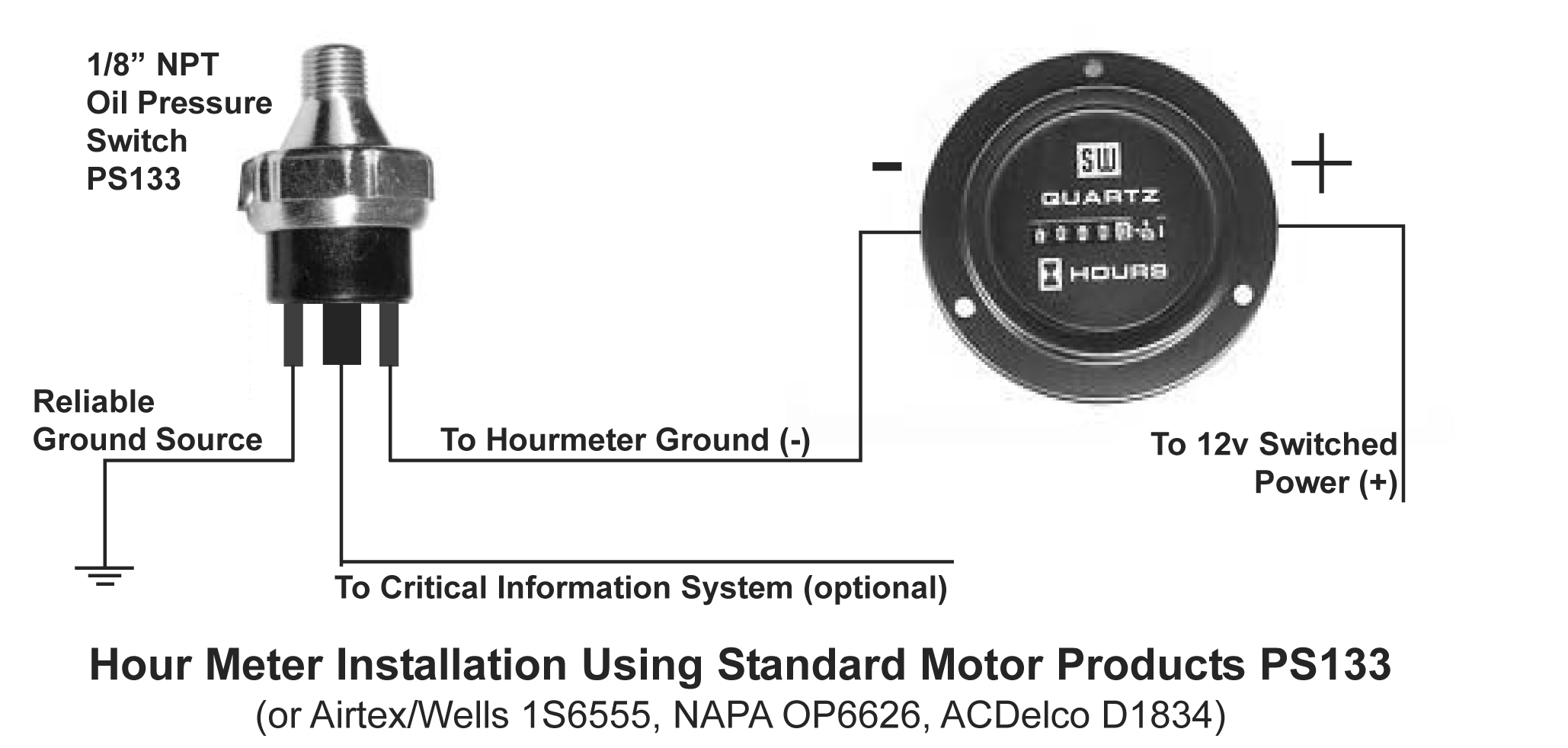
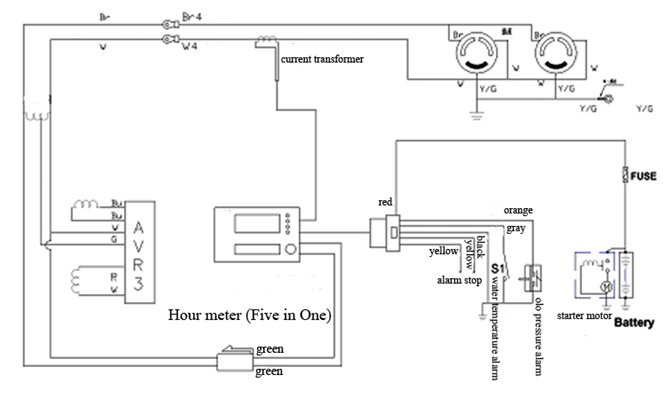 Hour Meter Engine Wiring Diagram
 Engine Hour Meter Wiring Diagram
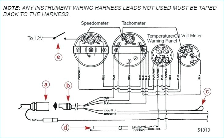 Suzuki Outboard Tachometer Wiring Diagram - Drivenheisenberg
 Hour Meter Installation Instructions

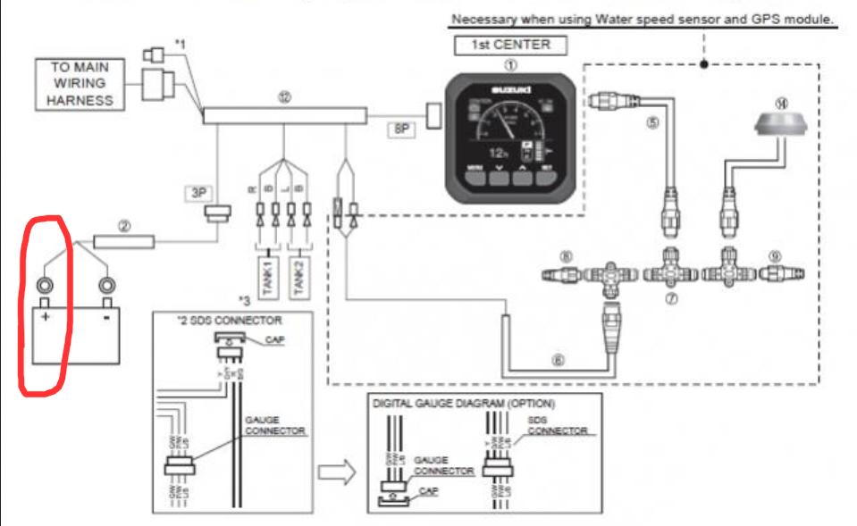 Suzuki Multifunction Gauge Wiring Diagram - Artsied
 Suzuki Outboard Multifunction Gauge Wiring Diagram Images - Faceitsaloncom
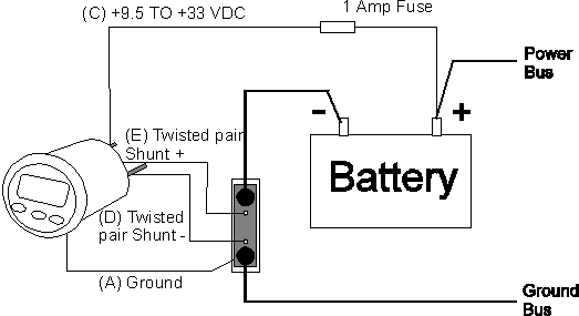
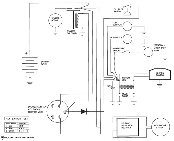 Engine Hour Meter Wiring Diagram - Uploadard
 Engine Hour Meter Wiring Diagram
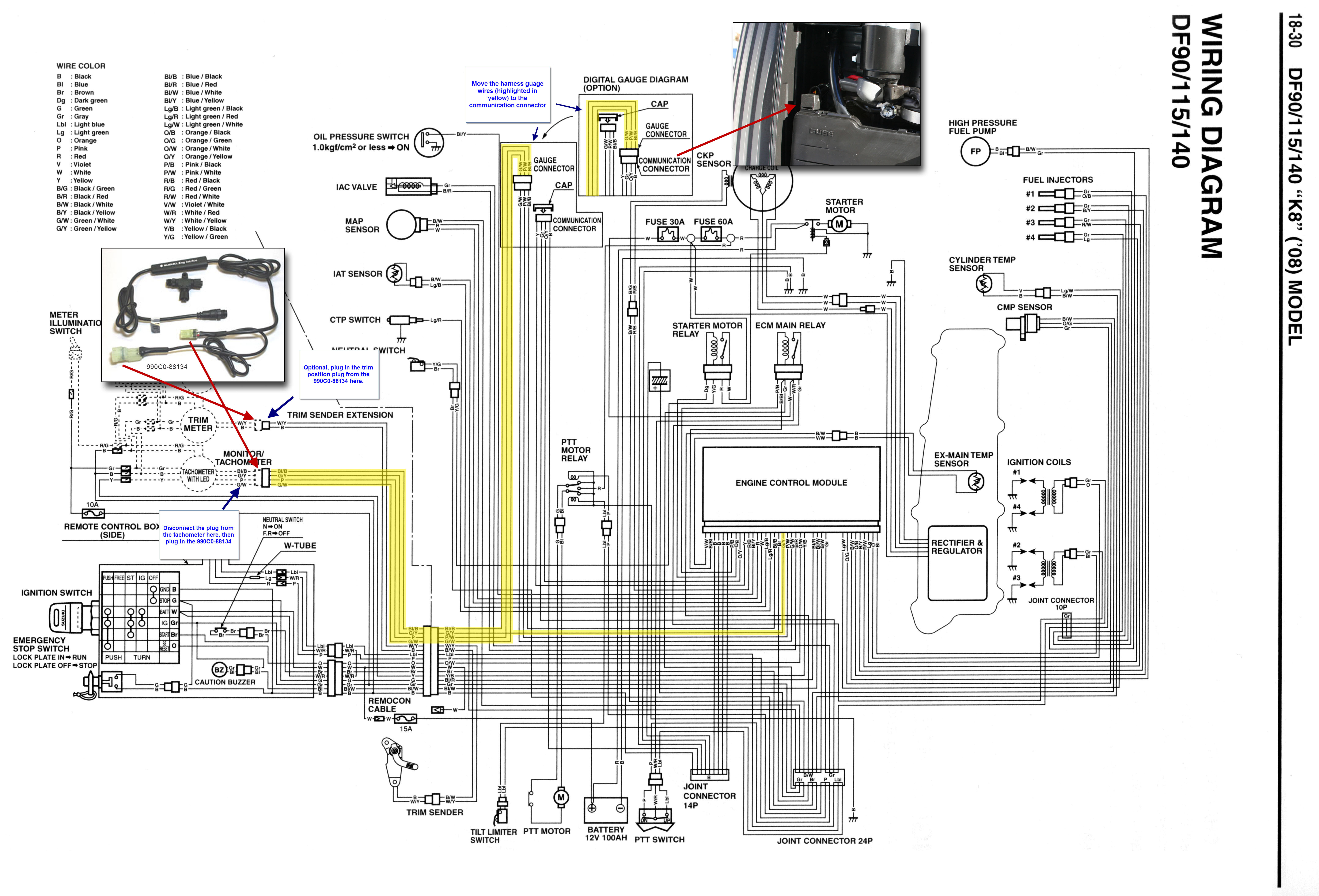 Suzuki Multifunction Gauge Wiring Diagram - Artsied
 How To Wire Hour Meter
