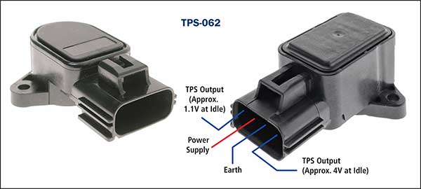
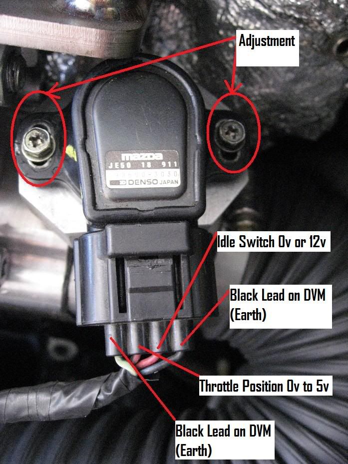
The TPS be in picture. is mounted 2 slotted screws it be rotated the throttle position adjustment. marked it's original position a knife (for accuracy!), then moved just knife-blades clockwise (i.e. the throttle have be little closed the TPS response).
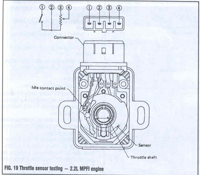 1999 2.5 RS 4-pin Throttle Position Sensor pin-out Registrations. 1999 2.5 RS 4-pin Throttle Position Sensor pin-out. . have of FSM wiring diagrams diagnostics etc infront me.but of tell what pin on 4-pin TPS this 2.5 RS. . Newer Generations Subaru discussion ; 1990 Present .
 Subaru pedal, metal arm.plastic/rubber pedal. possibly an STI pedal. into pedal, clip top ( were wiring colours the plug was cut loom ) Left =1 1- Dark Blue = Signal 2- Orange = Sensor Ground 3- Blue/Red = 5v 4- White/Blue = Signal 5- White/Red = Sensor Ground 6- Light Blue = 5v are 0-5v tracks upwards
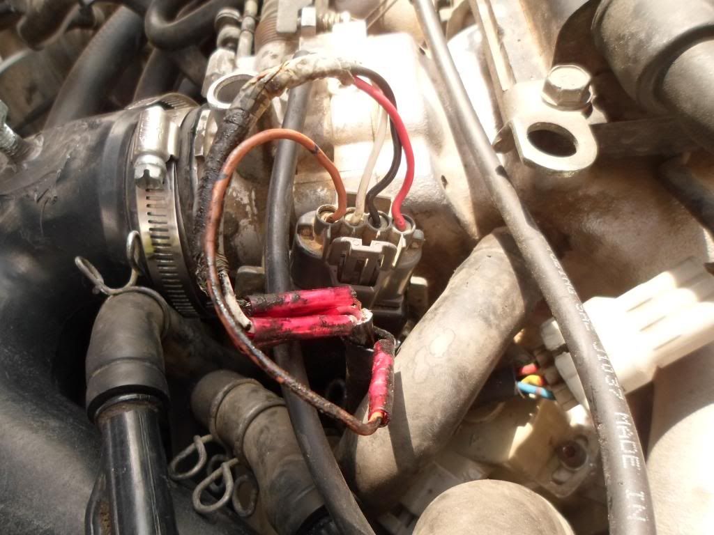 Step-by-Step Guide: Wiring 4 Pin Throttle Position Sensor. Wiring 4-pin throttle position sensor (TPS) be straightforward process you follow correct steps. TPS plays crucial role the operation a vehicle's engine, it feedback the engine control unit (ECU) the position the throttle.
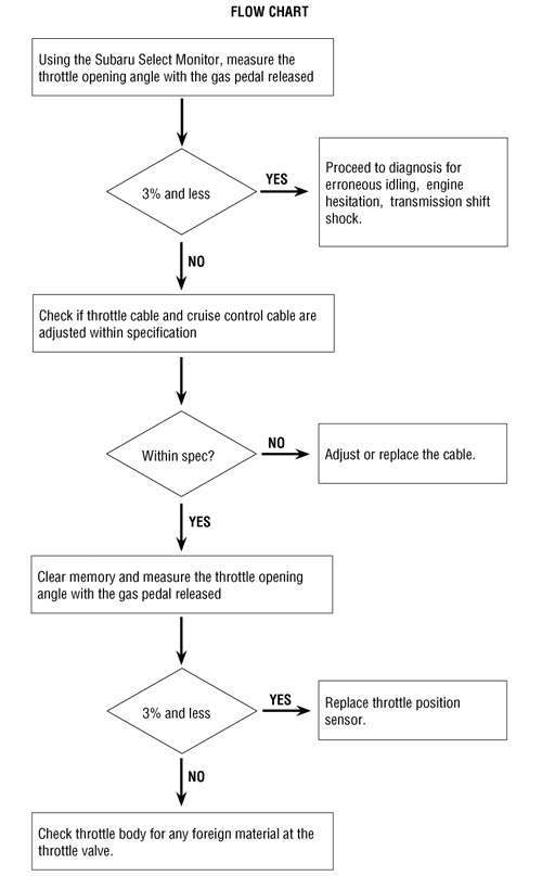 Vehicle Application: 1997 Subaru Legacy SUS 2.5L Customer Concern: check engine light on a code P0122 Throttle Position Sensor (TPS) signal. TPS sensor replaced. Tests/Procedures: 1. Verify Red wire 5-volts the TPS sensor the Black wire a good ground. 2.
 to provide SUBARU service personnel the information data the correct maintenance repair SUBARU vehicles. . at wiring diagram check system's circuit. check switch, relay, fuse, ground, etc. 4. LOCATION REPAIR TROUBLE
 All measurements at ECU I presume signal wire ground. the MY97 TPS three wires 1)Black - ground, 2)Red - Supply 3)White - signal. . Don, please. have diagrams the ECU the specific terminals set TPS when remove ECU, see block connectors 4x9 pins (I .
 Throttle Position Sensor (TPS) Plug Subaru Alternative Part Names: Throttle Position Sensor Plug; Throttle Position Sensor Plug; TPS Plug Subaru Part Numbers: 22633AA111; 22633AA110; 22633AA140 Wiring Diagram IDs: E7; E10; E13 Housing = Connector and lock (if applicable).Connector Kit = Connec
 4 Pin Throttle Position Sensor Wiring Diagram 4 Pin Throttle Sensor Harness Schematics. throttle valve sensor a type sensor in automotive applications monitor position the throttle. four-wire throttle valve sensor four wires, are signal wires, two earth hot. Signal Wire (Sensor 1) Signal Wire .

 6 Pin Throttle Position Sensor Wiring Diagram
 1999 Subaru Wiring Diagrams
 06 Subaru Impreza Wiring Diagram
 Throttle Position Sensor Wiring Diagram 👈 - JAN23 corysnanaa
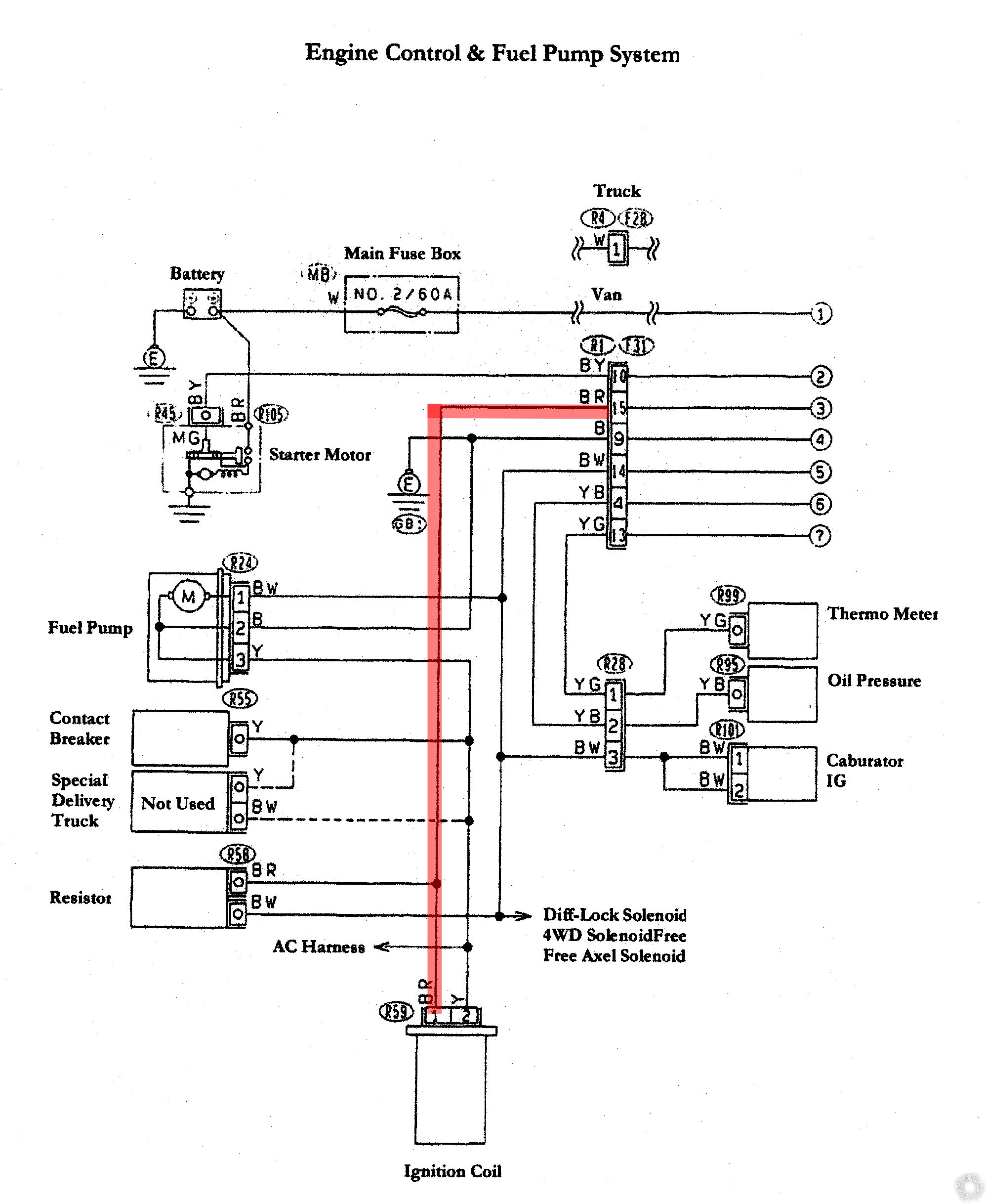 Subaru Wiring Diagram Color Codes - Wiring Diagram and Schematics
 Subaru Wiring Diagram Color Codes
 Fitech Tps Wiring Diagram
 Throttle Position Sensor Diagram & Wiring | JustAnswer
 Subaru Wiring Manual
 6 Pin Throttle Position Sensor Wiring Diagram Throttle Body Position
 | Repair Guides | Electronic Engine Controls | Throttle Position Sensor
