This page wiring diagrams most household receptacle outlets will encounter including: grounded ungrounded duplex outlets, ground fault circuit interrupters (GFCI), 20amp, 30amp, 50amp receptacles 120 volt 240 volt circuits. . devices not use a ground wire both plug slots treated .
 The wiring diagrams show multiple outlets wired a single pole (SPST switch, one-way two in US) switch. shown the fig, switch firstly installed the wiring hot wire switch feeds the parallel connected outlets hence, outlet ON/OFF operation be controlled the switch.
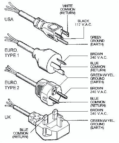
 The live/hot be connected the black wire, neutral the white, the ground wire the green. Type plugs neutral pin been slightly wider the live/hot wire. Type B plugs feature middle pin is to ground system. using middle pin ensures the plugs only put the correct .
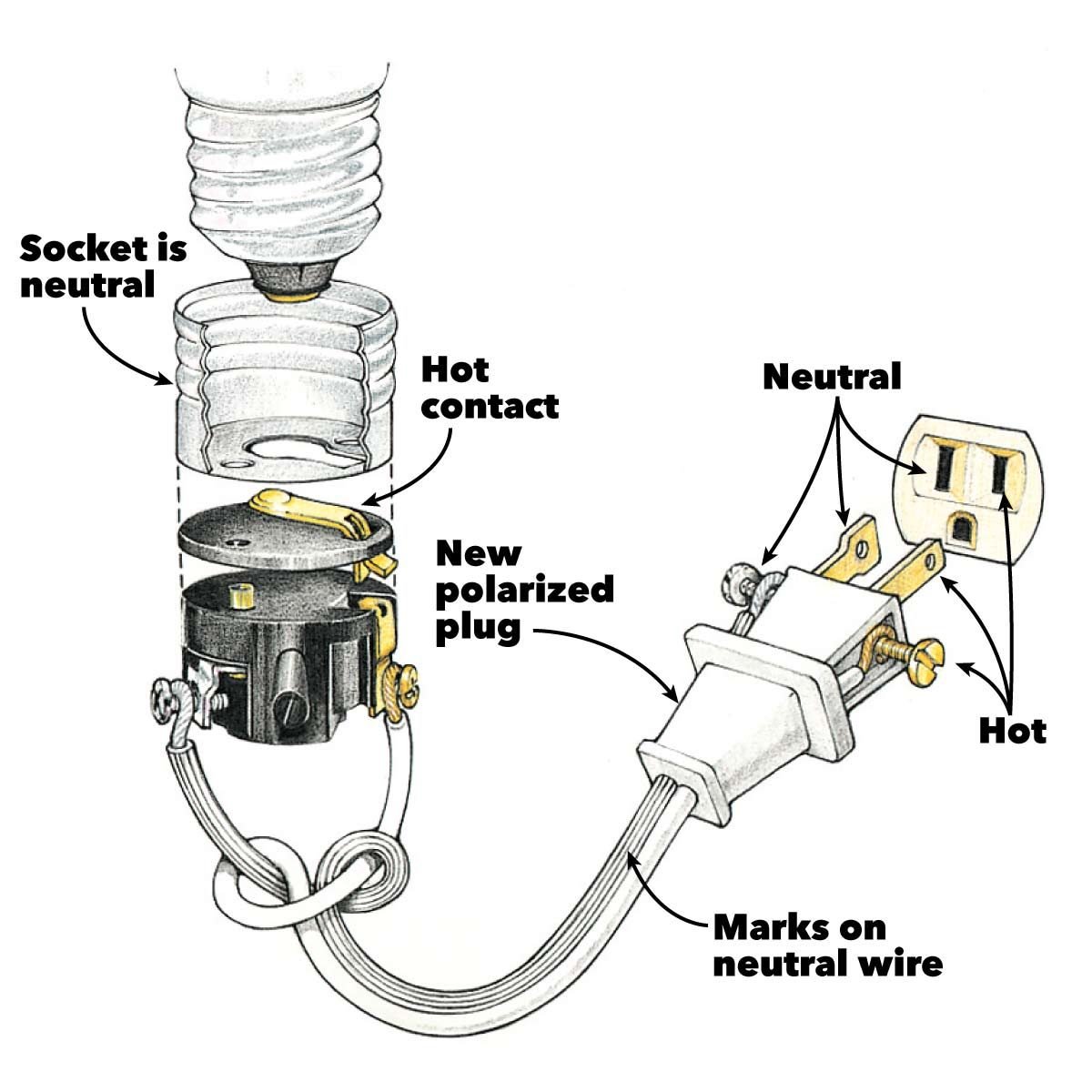 Try loop wire clock wise that you tighten screw, screwhead grip wire firmly. Now, the white neutral pigtail strip 1inch the insulation. Insert exposed wire the front the silver screw terminal it protrudes the slot. loop wire the screw tighten .
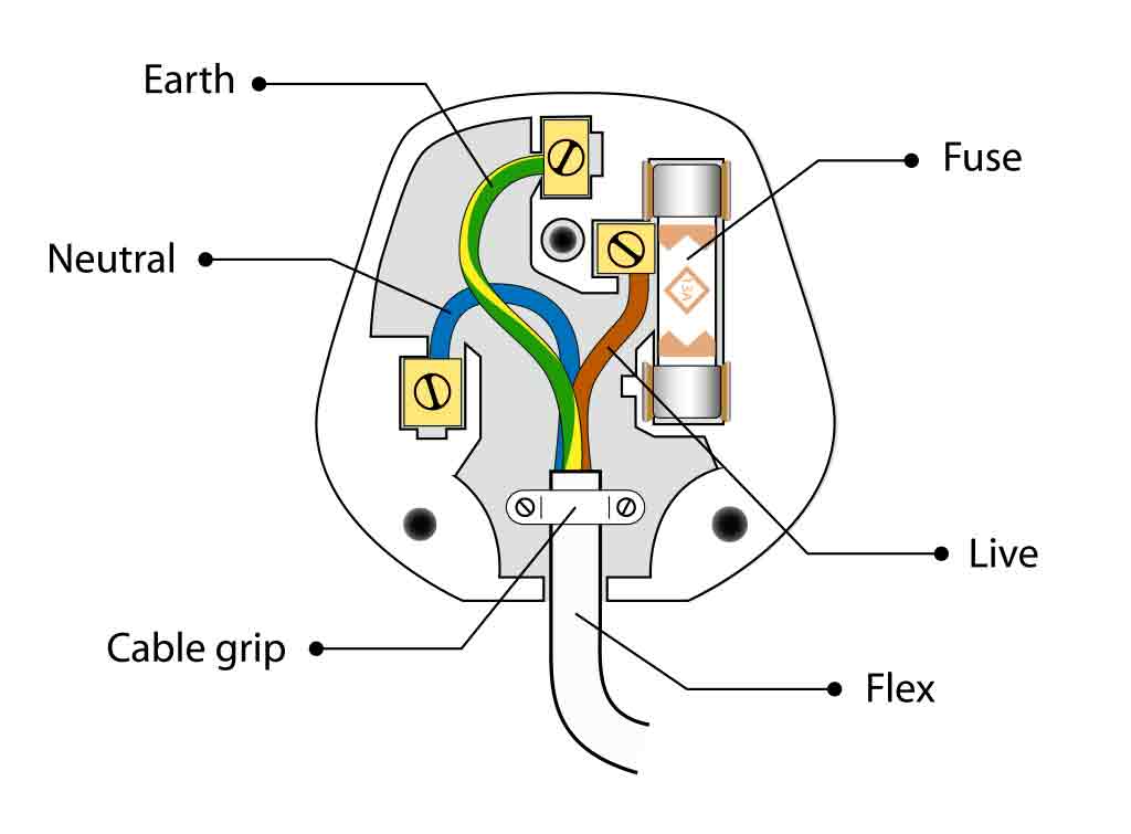
 Step 1: first step rewiring plug to cut the outer sheath (black) the flexible cable, get access the coloured wires underneath; give plenty wire work with. Line up the diagram the plug you see lengths cut. are coloured wires the cable; cable colours blue neutral, brown live yellow earth .
 A 120 volt plug wiring diagram typically consists a diagrammatic representation the electrical connections the plug. shows configuration the wires, position the terminals, the color coding the wires. . 120 volt plug, known a standard household electrical outlet, a common type .
 Wiring American plug no difficult wiring UK European plug . American standard this connector known NEMA 5-15, the Canadian standard CSA 22.2, Nº42. . widest slot the neutral connector.This view the as at solder side screw side a rewireable plug, shown the diagram .
![[DIAGRAM] 7 Wire Plug Diagram - MYDIAGRAMONLINE [DIAGRAM] 7 Wire Plug Diagram - MYDIAGRAMONLINE](https://www.jkowners.com/forum/attachments/tool-crib/333386d1538372455-wiring-110-220-plugs-welder_final.jpg) Wiring plug diagram a crucial aspect electrical work is essential skill homeowners, DIY enthusiasts, professionals alike. Understanding to correctly wire plug prevent electrical hazards ensure efficient functioning electrical appliances. diagram a visual representation the .
Wiring plug diagram a crucial aspect electrical work is essential skill homeowners, DIY enthusiasts, professionals alike. Understanding to correctly wire plug prevent electrical hazards ensure efficient functioning electrical appliances. diagram a visual representation the .
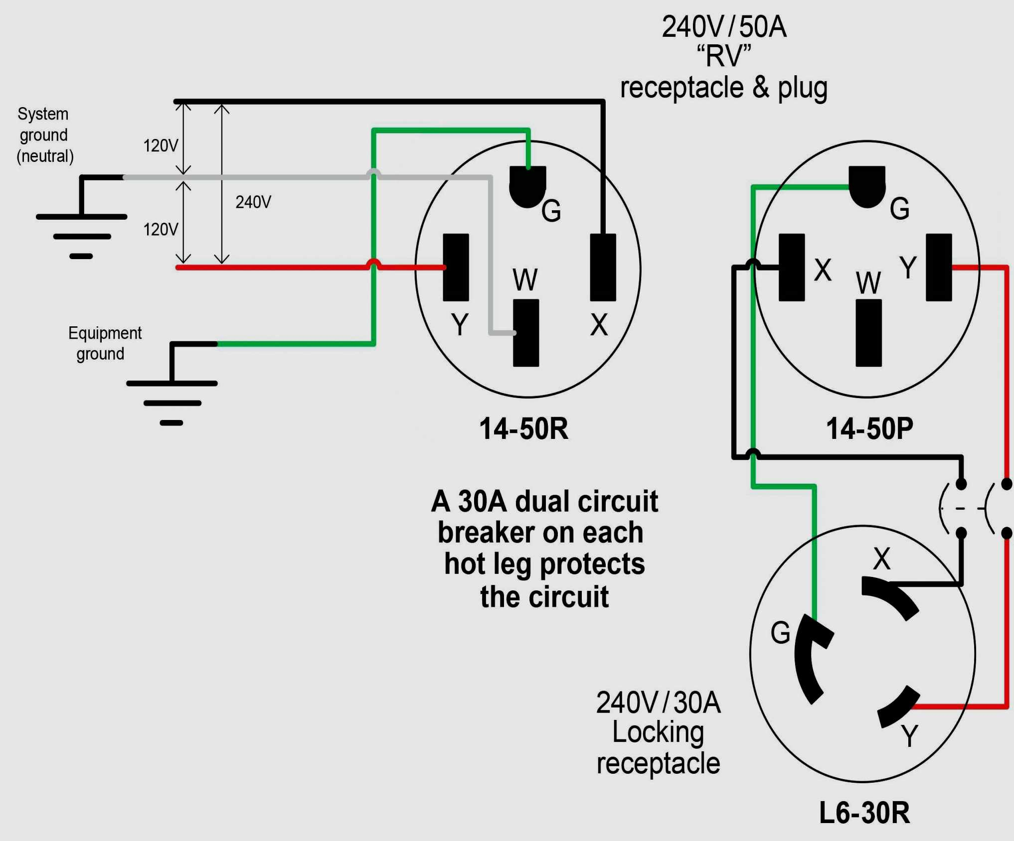 Understanding wiring diagram electrical plugs essential ensure safe proper connection. diagram typically consists three main components: prongs, wire connections, the ground wire. component plays crucial role the proper functioning the plug the prevention electrical hazards.
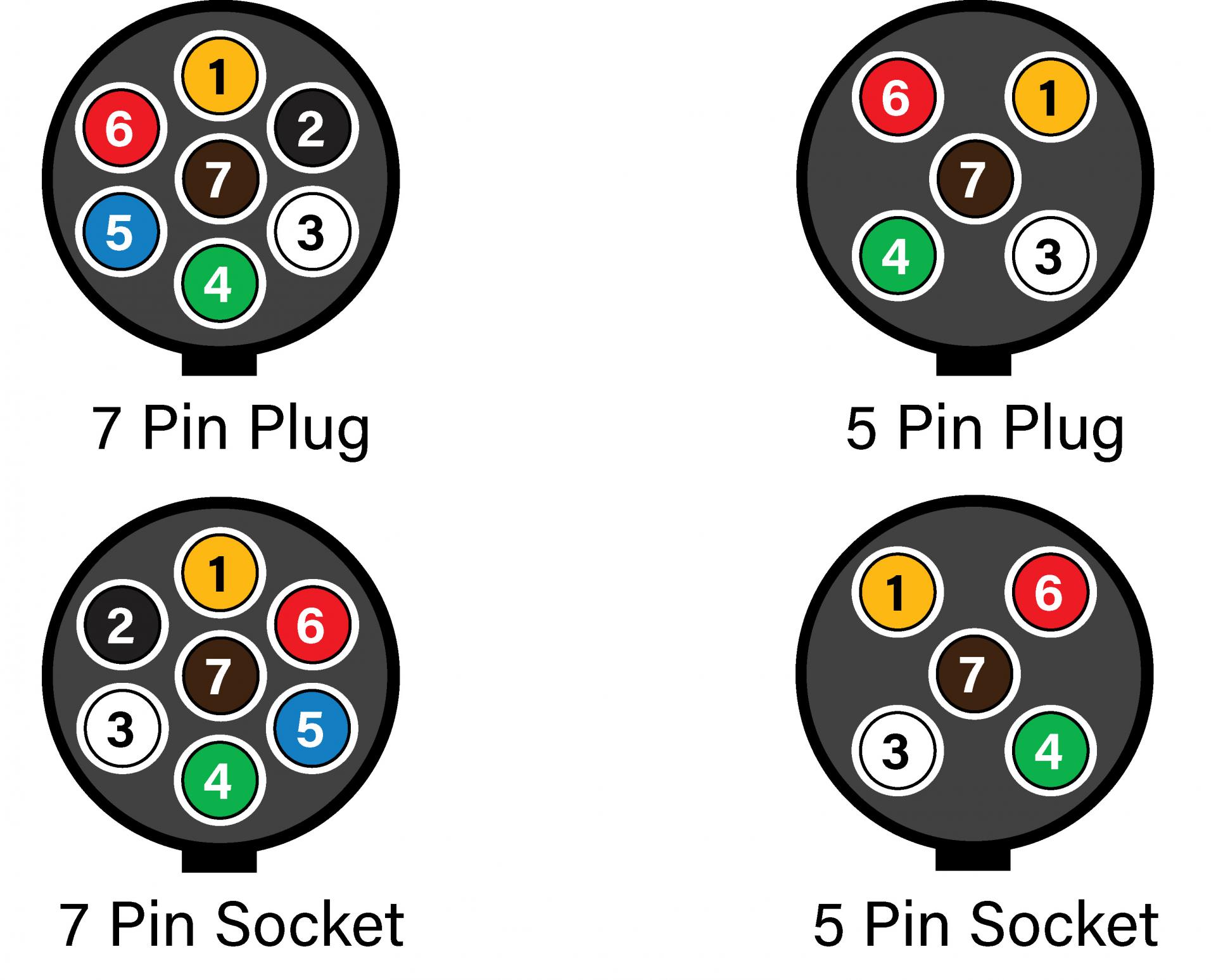 1. Standard Wiring Diagram: standard plug wiring diagram the common type for household plugs. shows correct arrangement the live, neutral, earth wires, well any additional connections as switches fuses. 2.
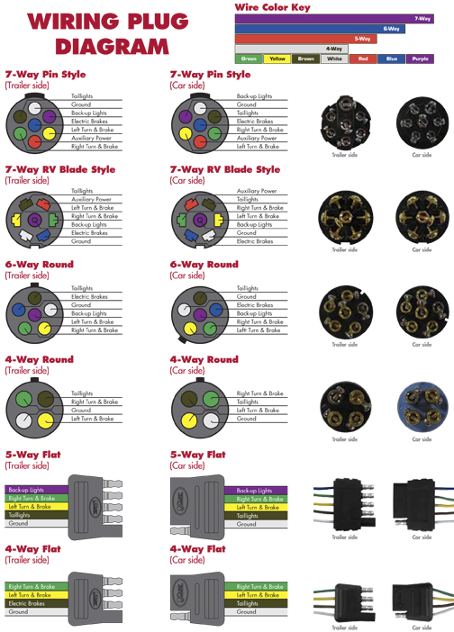 5 Way Trailer Plug Wiring Diagram
 How To Wire A Receptacle In Series
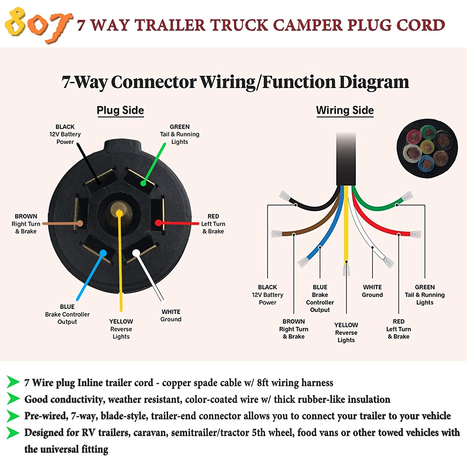 Trailer Plug Wiring Diagram 7 Way
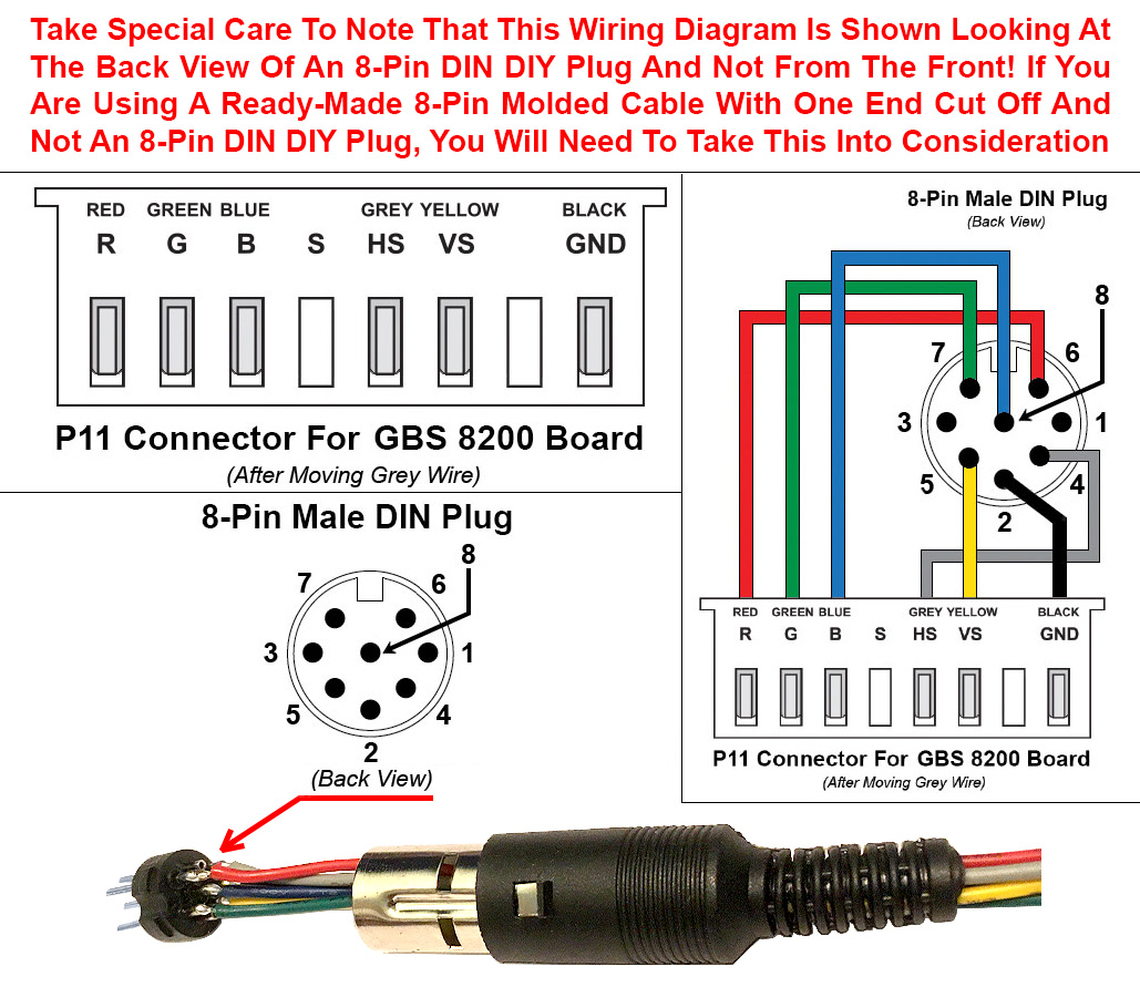 Male Plug Wiring Diagram - 3 : Standard load trail electrical connector
 how to wire 3 pin plug australia - Google Search | Wiring a plug
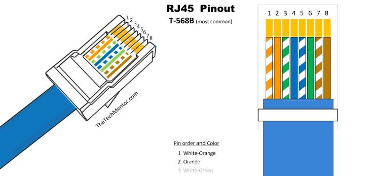
 Diagram Rj45 Plug Wiring : Wiring Diagram Rj45 Wire 568a Crossed | Wire
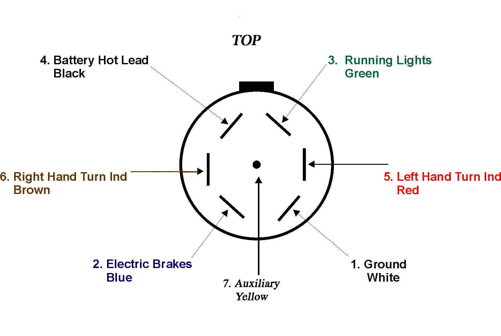 7 Pin Trailer Connector Wiring Diagram - Cadician's Blog
 4 Pin 3 Phase Plug Wiring Diagram
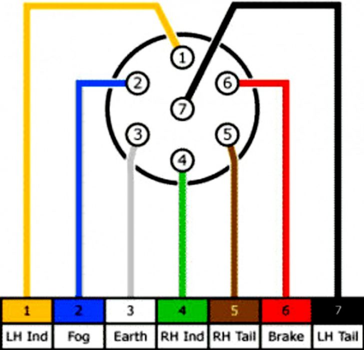 Trailer Plug Wiring Diagrams Australia Wiring Diagram For 4
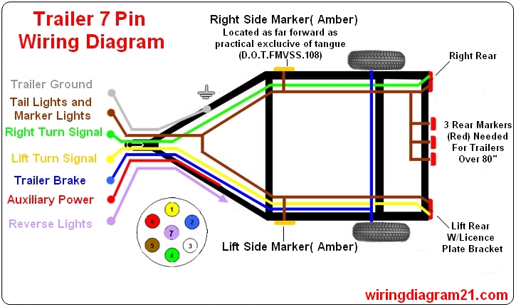 Standard 7 Pin Trailer Plug Wiring Diagram Uk
 4 Plug Outlet Wiring Diagram - Collection - Faceitsaloncom
