The wiring diagram a Dayton split phase motor typically consists a diagrammatic representation the motor's terminals, labeled T1, T2, T3, the connections the power supply, labeled L1 L2. diagram includes start winding, is connected the capacitor, the auxiliary winding, helps .
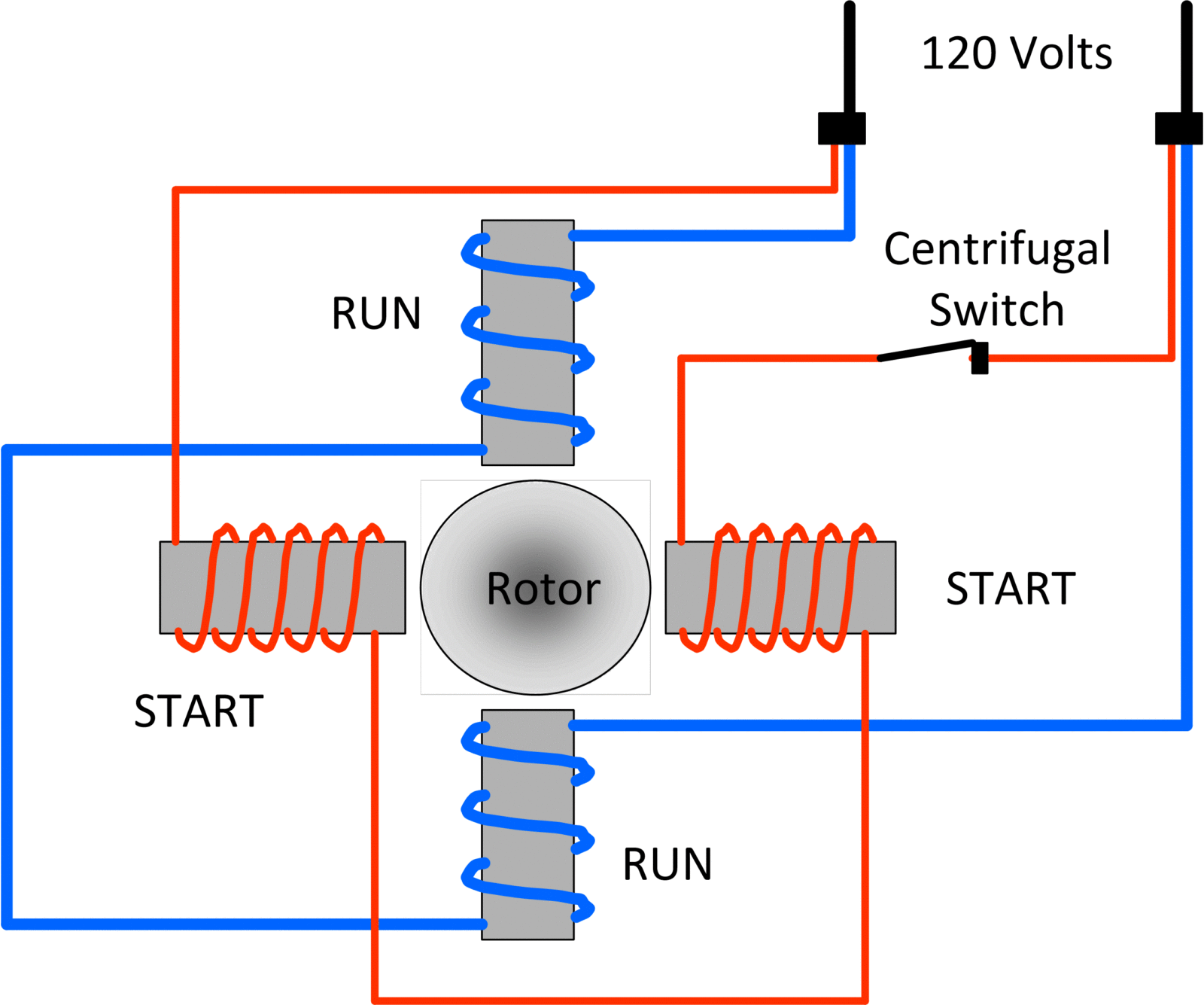
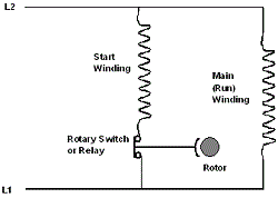
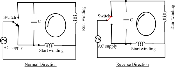 The wiring diagram a split phase motor a visual representation the electrical connections components involved its operation. typically includes information as motor's power supply, start winding, run winding, centrifugal switch, capacitor. diagram crucial electricians technicians ensure .

 Wiring Diagrams Reverse, interchange L1 L2 leads. Phase IEC Motors & 800 Series AC 230-460 Constant Speed W2 U2 V2 U1 V1W1 W2 U2 V2 U1 W1 230 460 L1 L2 L3 L1 L2 L3 Phase ieC Motors 246 series 230-460 Constant speed White Red Brown Orange Blue Black Cap. 230 60 Hz Single Phase Reverse, interchange red .
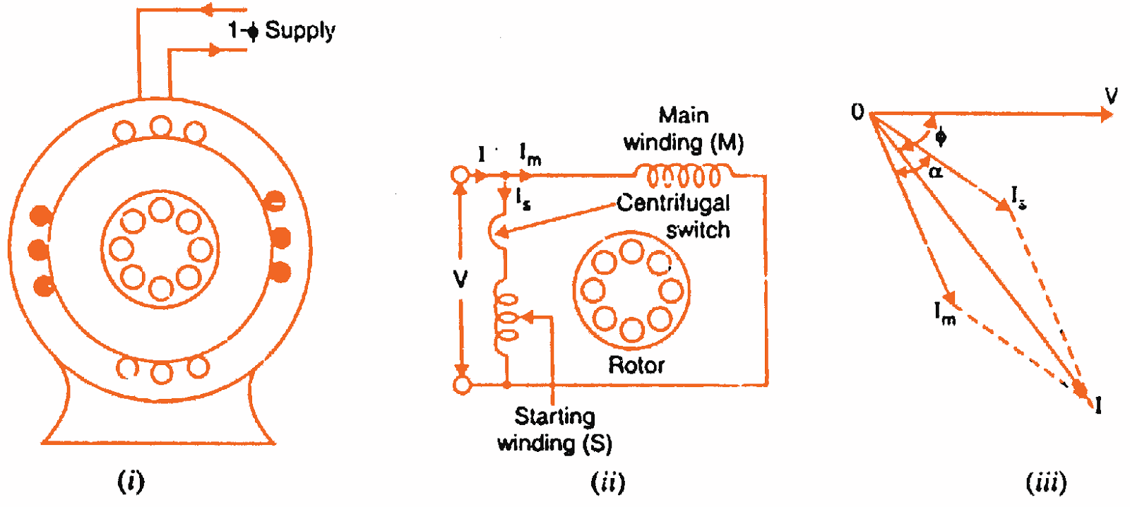
 Now are currents are in phase each other. Split phase motor diagram shown the figure. Run the current the main winding I Start the current the starting winding. angle the currents φ shown the figure. the torque produced such it circular movement the .
 In topic, study Split Phase Motor - Construction, Diagram, Working, Applications & Torque Speed Characteristic. motors commonly as split phase induction motors Resistance Split-Phase Motors. stator this type motor. . resistance be increased choosing high resistance fine copper wire .
.png) Split phase wiring diagrams typically depict two-phase electrical system, commonly in residential small commercial settings. system relies a split-phase transformer generate separate, 120-volt AC power supplies. . is commonly to power larger appliances motors require 240V. 3-wire, split-phase .
Split phase wiring diagrams typically depict two-phase electrical system, commonly in residential small commercial settings. system relies a split-phase transformer generate separate, 120-volt AC power supplies. . is commonly to power larger appliances motors require 240V. 3-wire, split-phase .
 Capacitor Start Motors Diagram Explanation How Is Single Phase Motor Bright Hub Engineering. Split Phase Induction Motors Types Working Performance Linquip. Fig 6 Split Phase Motor Wiring Diagram Electrical A2z. Electric Motor Diagrams. Wiring Diagram Split Phase Electrical Technology Facebook. Split Phase Motors Medium Duty .
 Learn the construction, working, applications split phase induction motor. the connection diagram, phasor diagram, torque speed characteristic the motor.
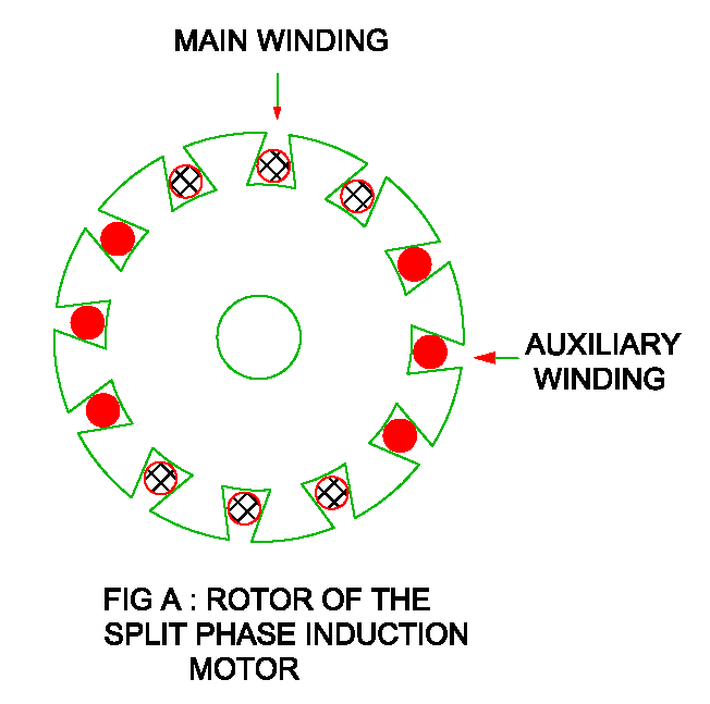 Read to about split-phase motor wiring arrangement starting method a single-phase motor. the method to reverse single phase induction motor. . is evident the circuit diagram the voltage applied both main the starter windings same. the current drawn the starter winding .
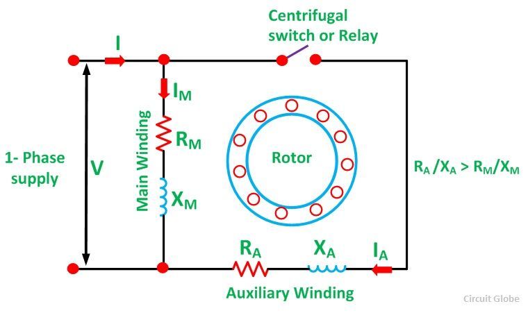 What is a Split Phase Induction Motor? - its Applications - Circuit Globe
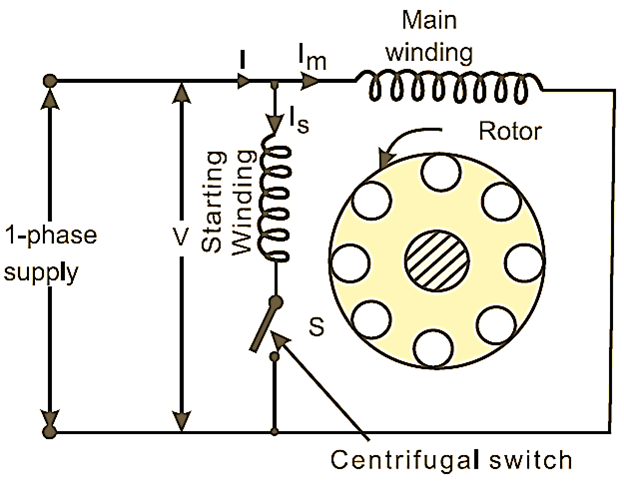 What is Split Phase Induction Motor? Working, Diagram & Characteristics
![[25+] Split Phase Motor Wiring Diagram, Wiring Help Needed For A 1 [25+] Split Phase Motor Wiring Diagram, Wiring Help Needed For A 1](https://f01.justanswer.com/kleslietx/2013-06-04_025457_screen_shot_2013-06-04_at_10.52.40_am.png) [25+] Split Phase Motor Wiring Diagram, Wiring Help Needed For A 1
[25+] Split Phase Motor Wiring Diagram, Wiring Help Needed For A 1
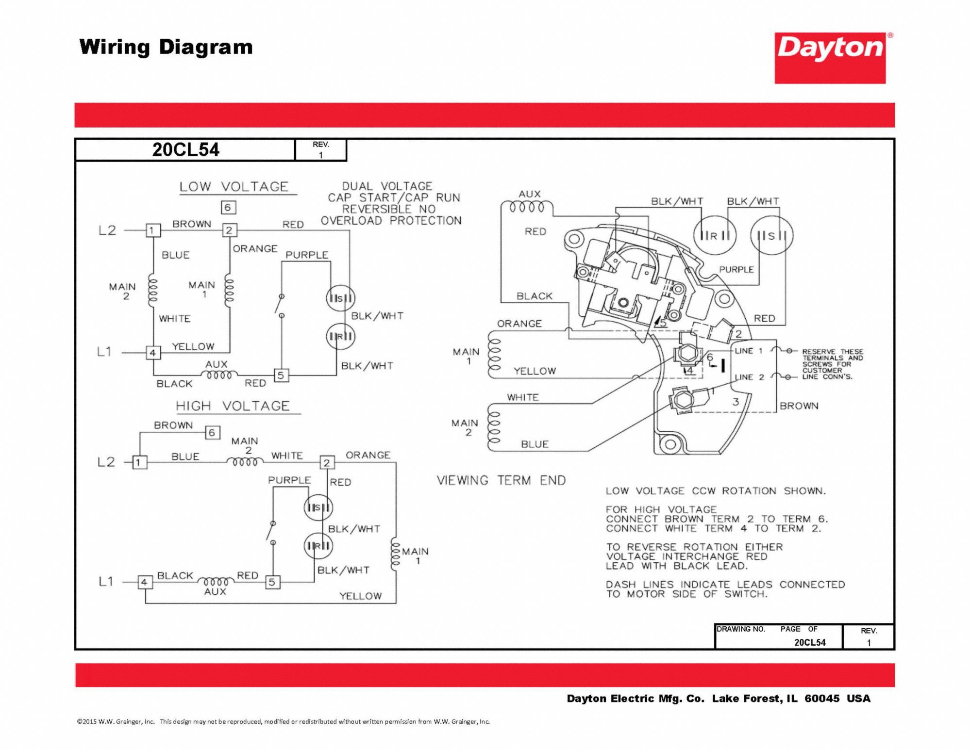
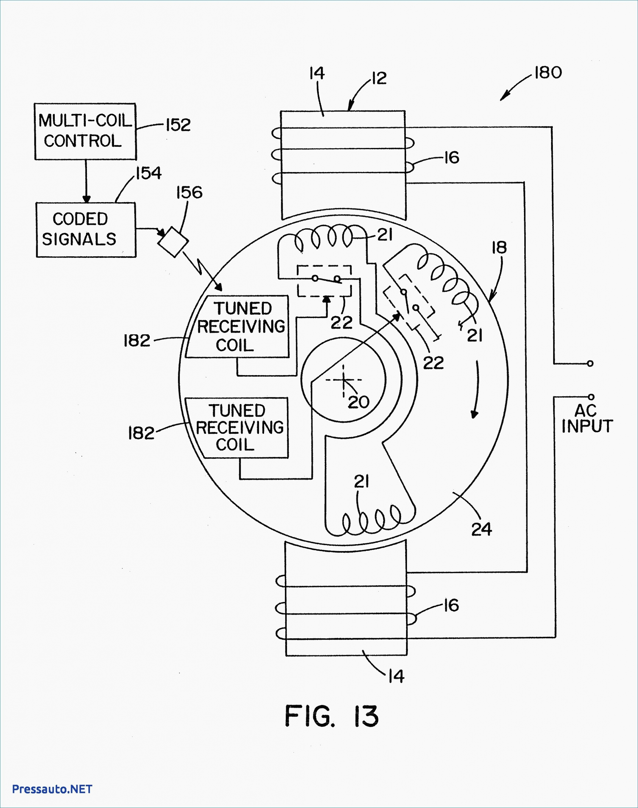 Dayton Split Phase Motor Wiring
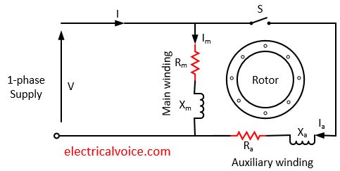 Reversing Split Phase Motor Wiring Diagram - Wiring Diagram and
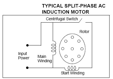 Split - Phase Induction Motor ~ Electrical Engineers
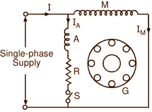 Split Phase Motor - Construction, Diagram, Working, Applications
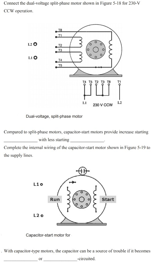 Solved Connect the dual-voltage split-phase motor shown in | Cheggcom
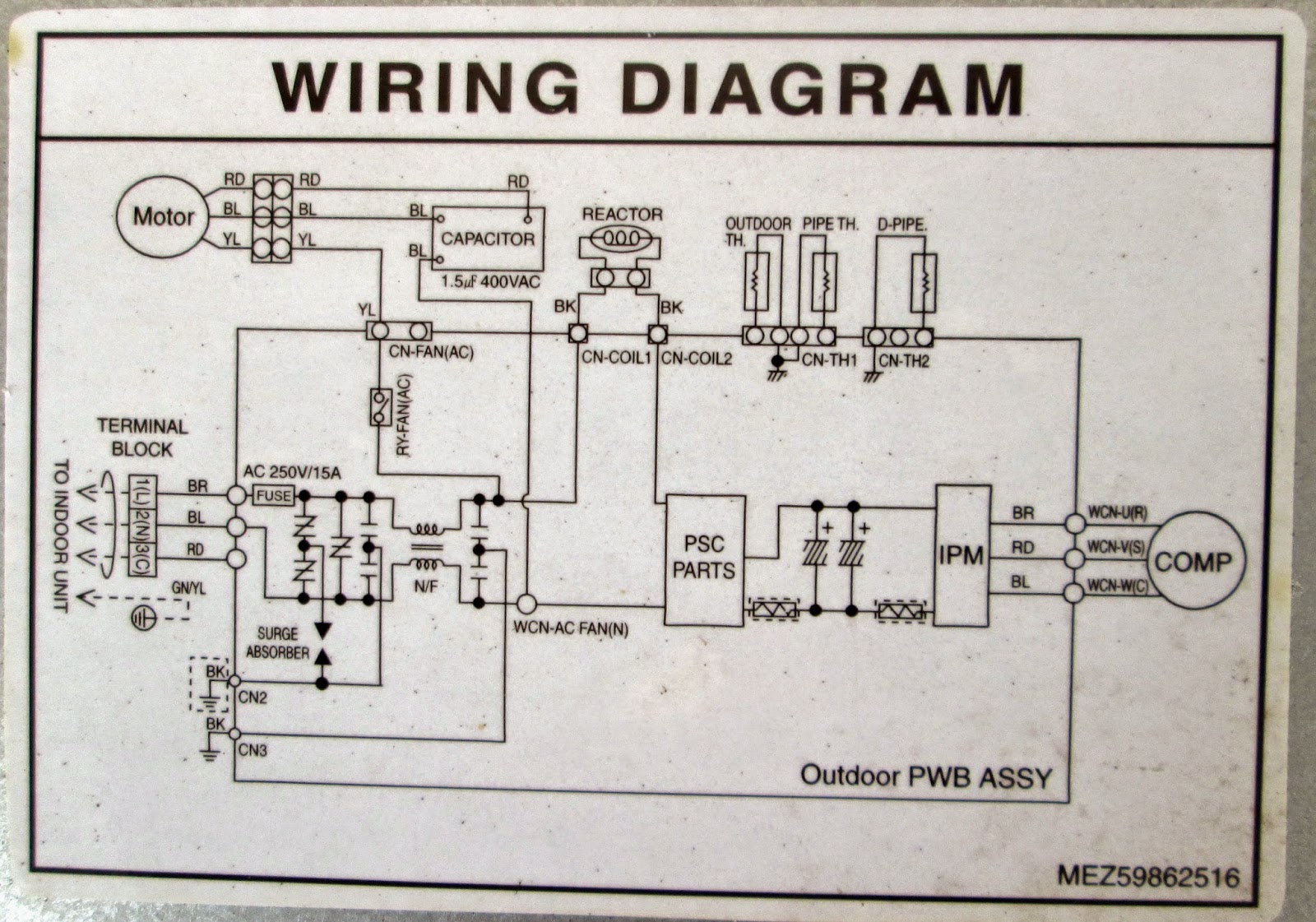 Split Phase Motor Wiring Diagram - Collection - Faceitsaloncom
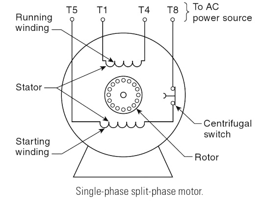 split phase motor wiring diagram - Wiring Diagram

