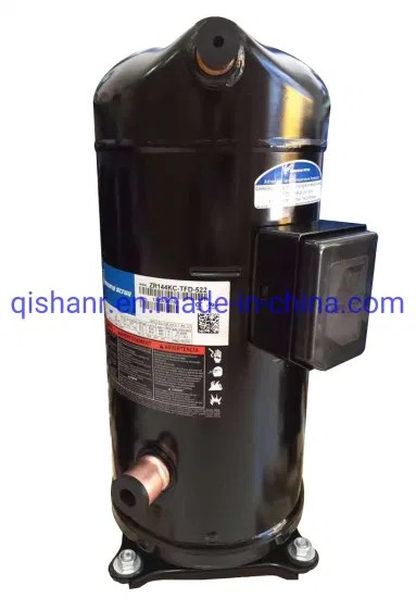
The Copeland Scroll Compressor single-phase wiring diagram simplifies user experience provides detailed instruction setup installation. this type compressor, motor works two stages. first stage the starting phase, is known the start winding. part the diagram explains the motor .
 Series Electrical Wiring Diagram ZB15 ~ ZB114 Single Phase Circuit (ZB15-ZB29) Electrical Schematics L1/N/PE: Single Phase Lines (line/neutral/ground) Q1: Manual Switch F1/F6: Fuse K1: Compressor Contactor Control Circuit C2: Run Capacitor M: Compressor Motor R/C/S: Compressor Terminal 3 Phase (ZB15-ZB114) (with Motor Protection Code "F .
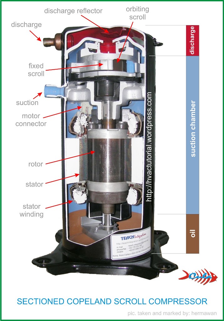
 As such, a understanding wiring diagrams the components key successful installation maintenance these systems. this article, we'll a deep dive Copeland scroll compressor single phase wiring diagrams, covering key elements, HVAC symbols, more. Components a Copeland Scroll .
 The compressor be put full operation the load limits this voltage range. 3.2 Frequency Copeland Scroll compressors available 50 Hz / 60 Hz voltage supply. use a 50 Hz single three-phase motor 60 Hz vice-versa possible. this instance following calculation factors .
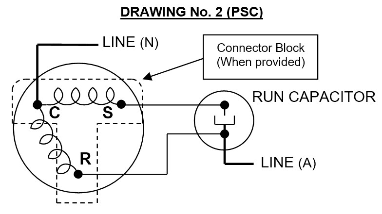
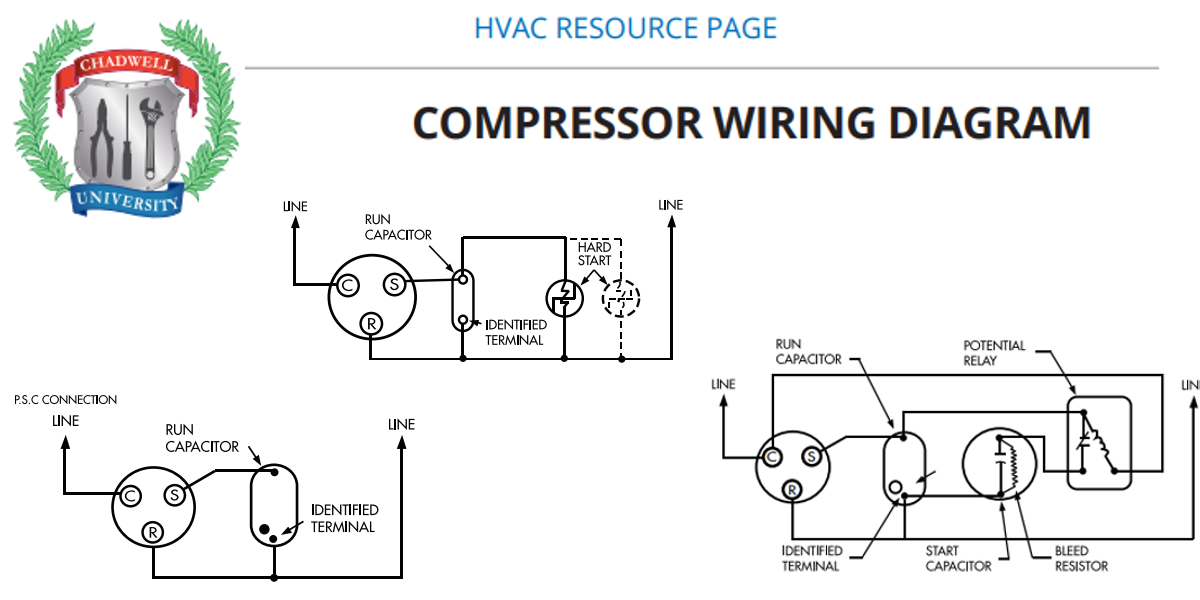
 The single-phase wiring diagram designed single-phase electrical systems, are commonly in residential small commercial buildings. consists a start capacitor, run capacitor, potential relay, connected series. start capacitor a boost power start compressor, the run capacitor .
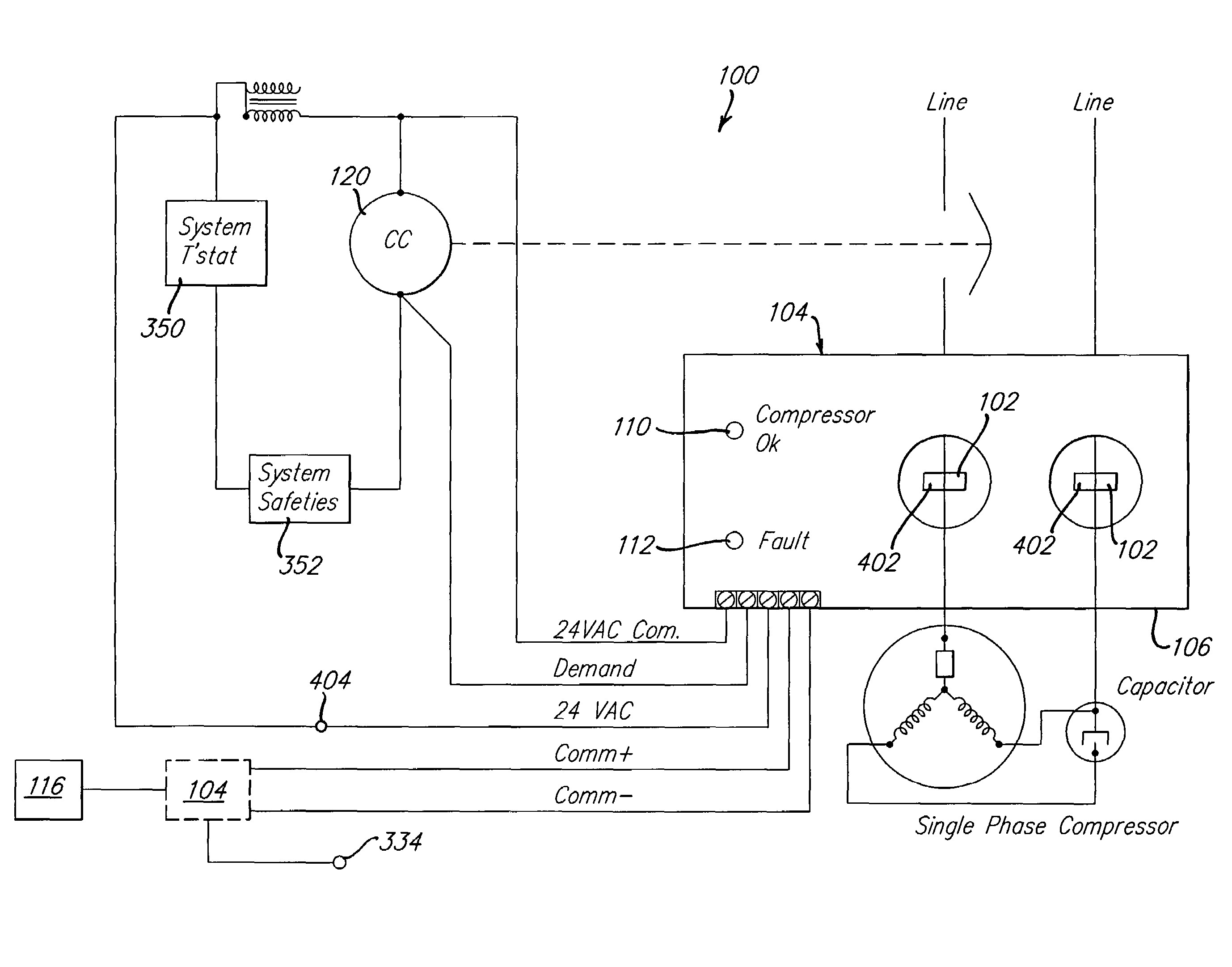
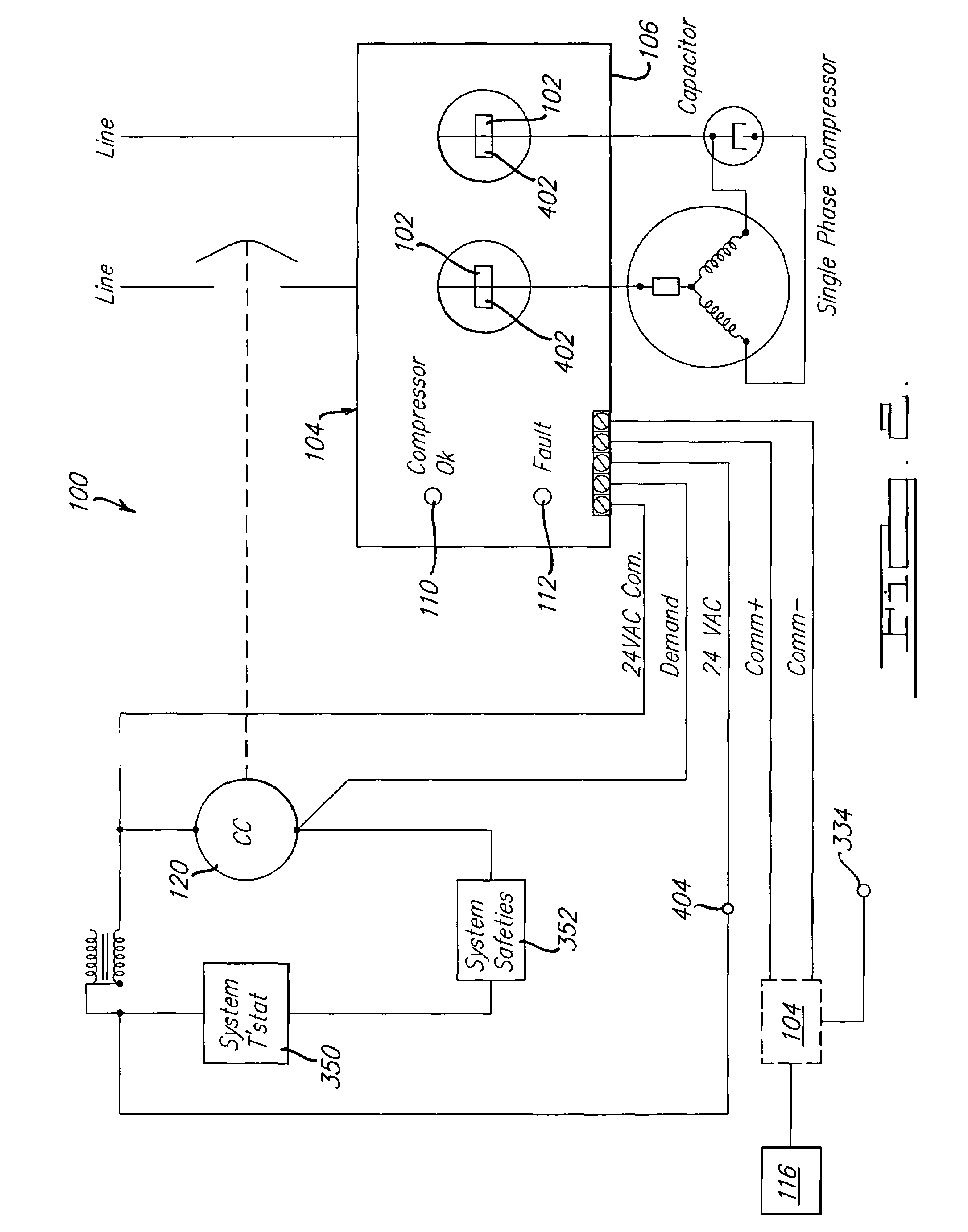
 The wiring diagram a single phase compressor typically show to connect capacitors, well the motor power supply wires. . wiring diagram a scroll compressor typically includes connections the main winding, start winding (if applicable), capacitor, potential relay motor starting. .
 Copeland scroll compressor wiring diagrams seem daunting first glance, with structured approach, become easily understandable. . Single-phase wiring typically for smaller compressors. diagram show simpler connection two main power supply lines (L1 L2), common terminal, connections .
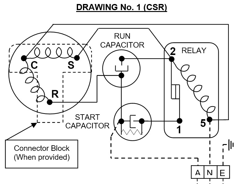 The single-phase wiring diagram a Copeland scroll compressor relatively simple, it be easily understood following steps below. 1. Identify terminals the compressor. terminals a Copeland scroll compressor typically labeled T1, T2, C. T1 T2 the terminals the power supply, C the common .
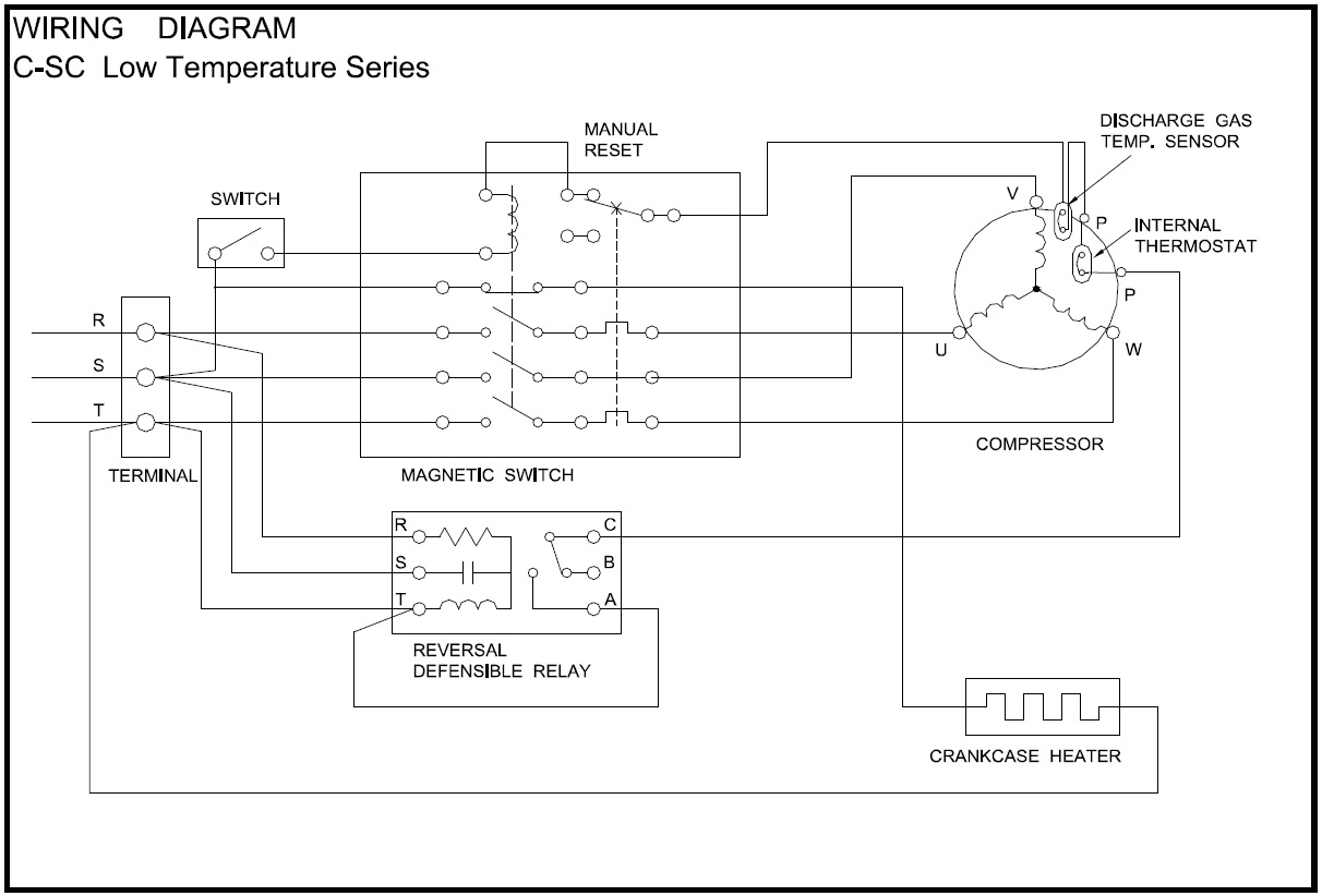
 The Copeland Scroll Compressor Single Phase Wiring Diagram essentially map outlines electrical connections circuitry the compressor. diagram essential technicians installers it them understand wiring connections needed proper installation maintenance.
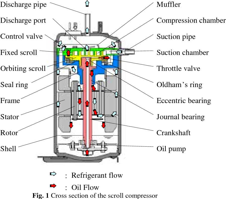 The wiring diagram a single phase scroll compressor designed show the components this complex system connected together. diagram includes connectors, wires, terminals are to connect compressor the parts the AC unit.
 Copeland Scroll Compressor Wiring Diagram For Your Needs
 Single Phase Scroll Compressor Wiring Diagram - Wiring Diagram and
 Single Phase Scroll Compressor Wiring Diagram - Circuit Diagram
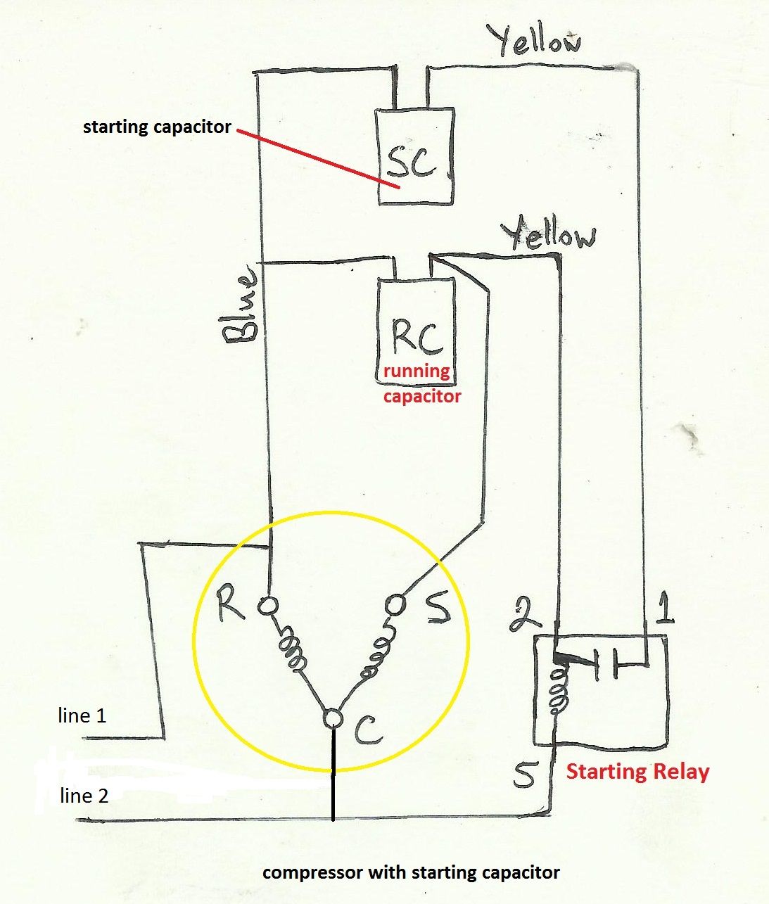 Single Phase Air Compressor Wiring Diagram
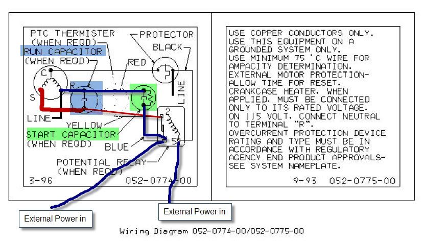 Copeland Scroll Compressor Wiring Diagram
 Single Phase Scroll Compressor Wiring Diagram - Circuit Diagram
 Single Phase Scroll Compressor Wiring Diagram - Circuit Diagram
 Copeland Scroll Compressor Wiring Diagram
 Ac Compressor Wire Diagram
 Air Compressor Wiring Diagram 230V 1 Phase - Cadician's Blog
 Single Phase Compressor | Engineers CommonRoom ।Electrical Circuit

