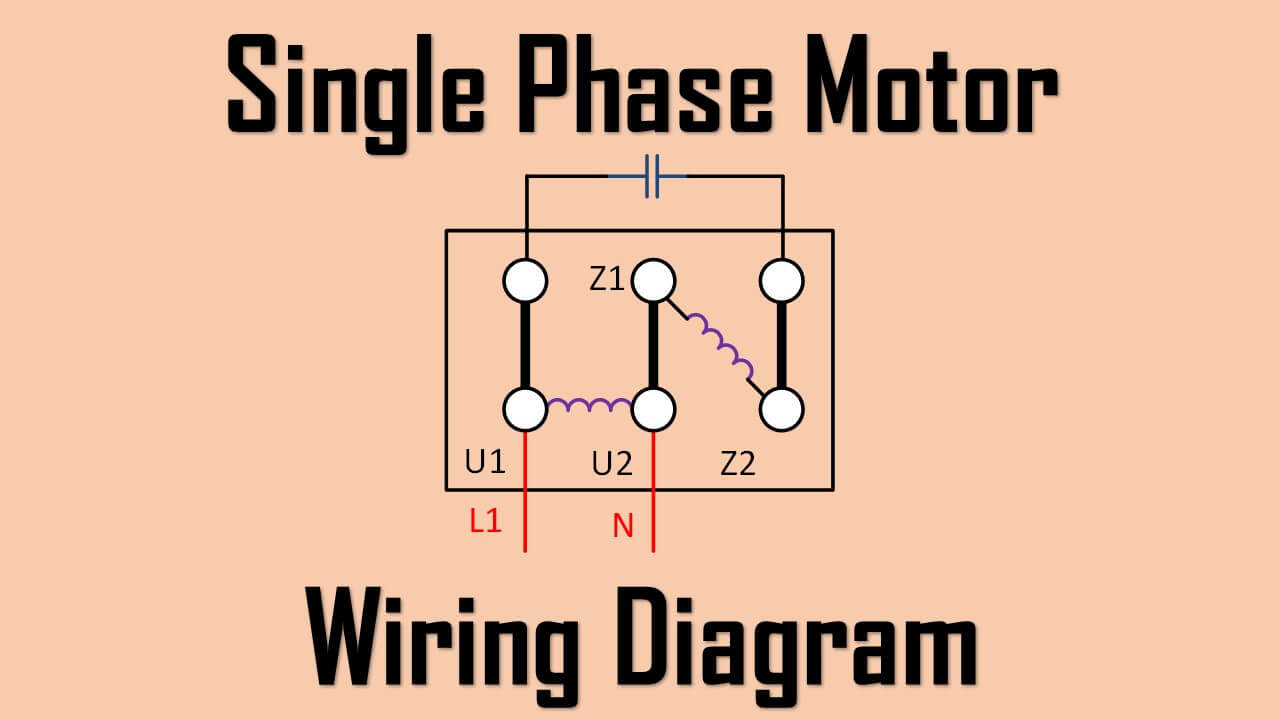
We learn single type single phase motor schematic single phase motors have schematic, connection, purpose. is learning type can find a good thing. Single Phase Motor Wiring Diagram. Single phase induction motor an AC motor operates supplied a single phase power.
 Single Phase Electric Motor Wiring Diagrams, Terminal Connections, Frame Sizes, Electric Motor Information - Updated March 20, 2024 . TERMINAL CONNECTIONS CAPACITOR START SINGLE-PHASE MOTORS. Motor Rotation Terminal Connections - Single Voltage. ROTATION L1 L2; Clockwise: 1,5: 4,8: Counter Clockwise: 1,8: 4,5:
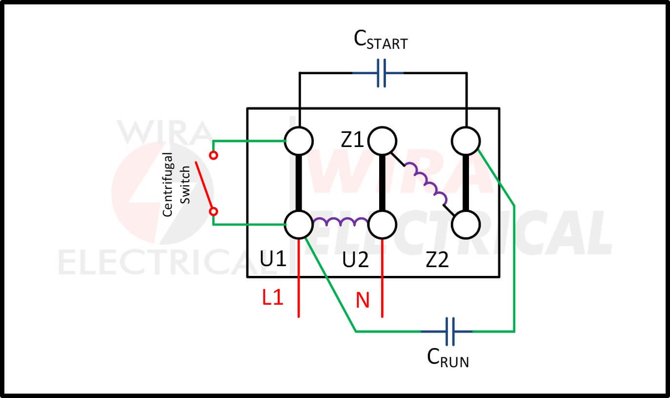 A single phase motor wiring diagram a visual representation the motor's electrical connections. shows the components terminals the motor connected, allowing electrical engineers technicians properly install troubleshoot motor.
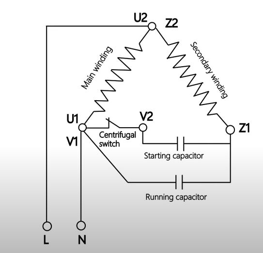 Step-by-Step Guide Wiring Diagrams 120 Volt Single Phase Motors. Wiring diagrams essential understanding electrical connections a motor. this step-by-step guide, will walk through process wiring 120 volt single phase motor. you a beginner have experience electrical work, .
 The motor wiring diagram a visual representation the electrical connections a single-phase motor. illustrates the components, as power supply, start capacitor, run capacitor, centrifugal switch, winding connections, connected each other.
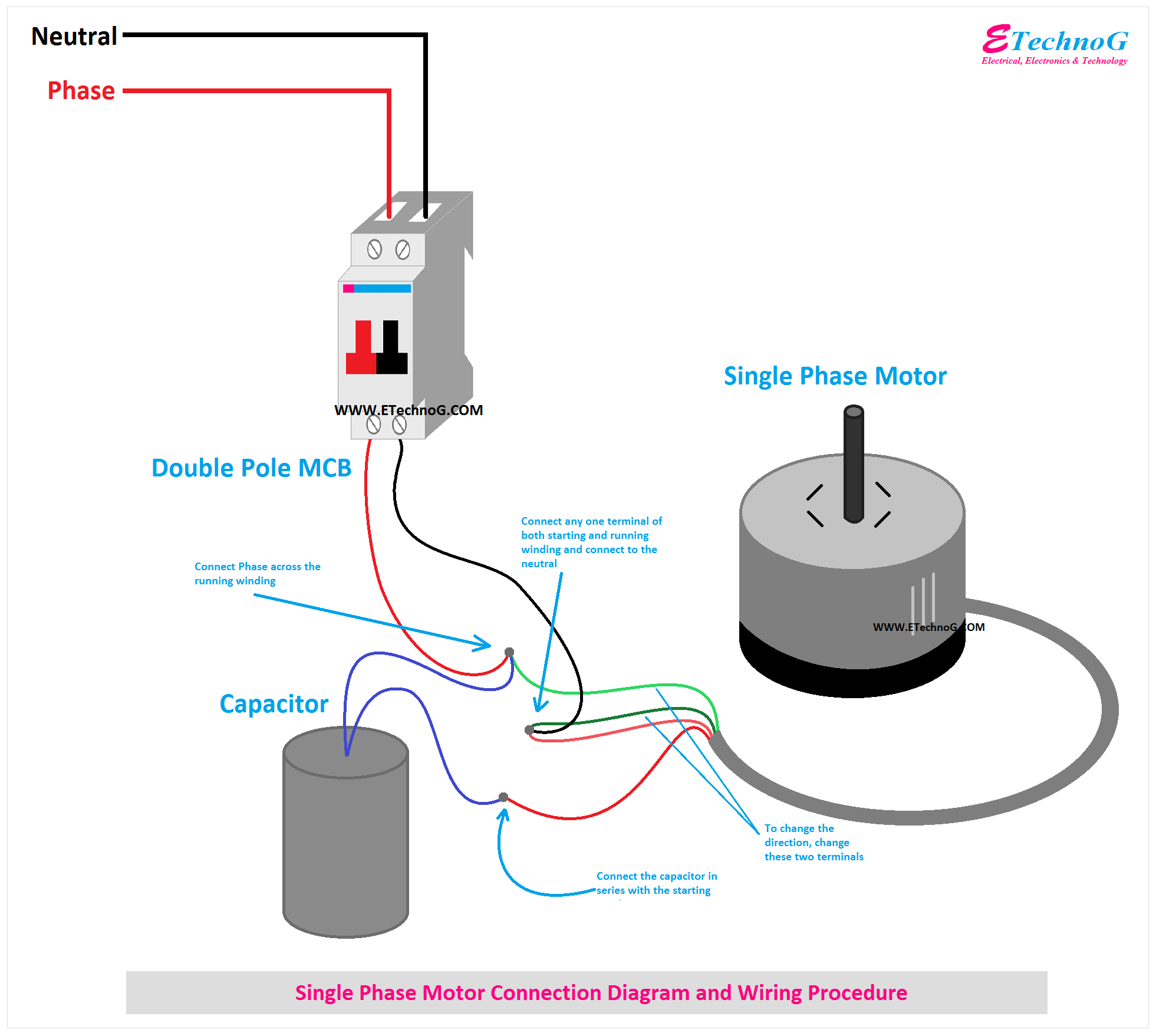
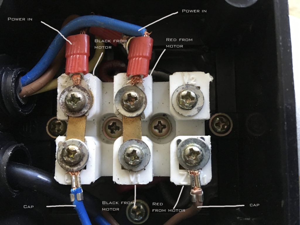 Wiring diagrams single phase motors provide visual representations the electrical connections components involved operating single phase motor. diagrams essential understanding wiring configurations troubleshooting issues may arise. typical wiring diagram a single phase motor includes .

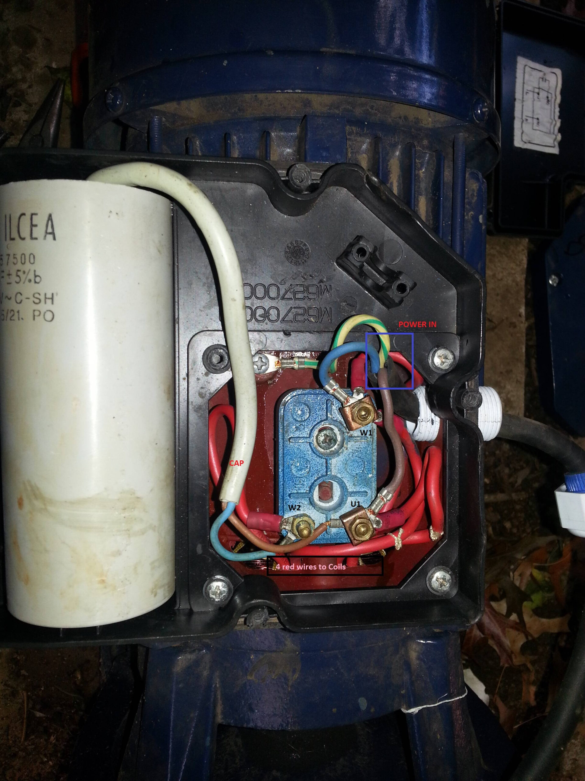 Single-phase motor connection wiring diagrams provide visual representation how motor be connected the power supply other components. diagrams typically show main components the motor, as stator, rotor, various terminals. terminal a specific purpose must connected correctly .
 The diagram a complete method single-phase motor wiring a circuit breaker contactor. the one-phase motor wiring first connect 2 pole circuit breaker after that, connect supply the motor starter I cont actor coil wiring Normally Close push button switch Normally Open push button switch in I connection capacitor .

 Wiring the Single Phase Motor: A Diagram Guide - WireMystique
 Motor Wiring Diagram Single Phase - Eneco
 How To Make Single phase Motor Wiring With Contactor Diagram | Motor
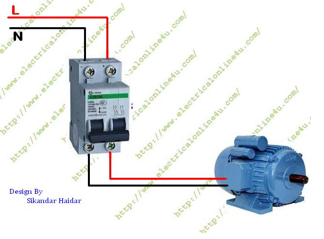 How to wire Single Phase Motor From Two Pole Circuit Breaker
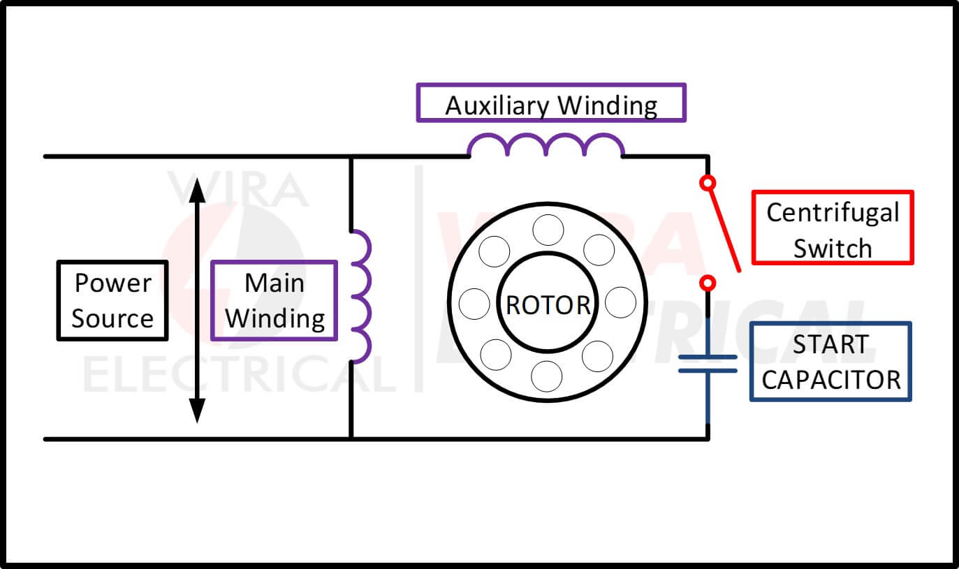 Single Phase Motor Wiring Diagram and Examples | Wira Electrical
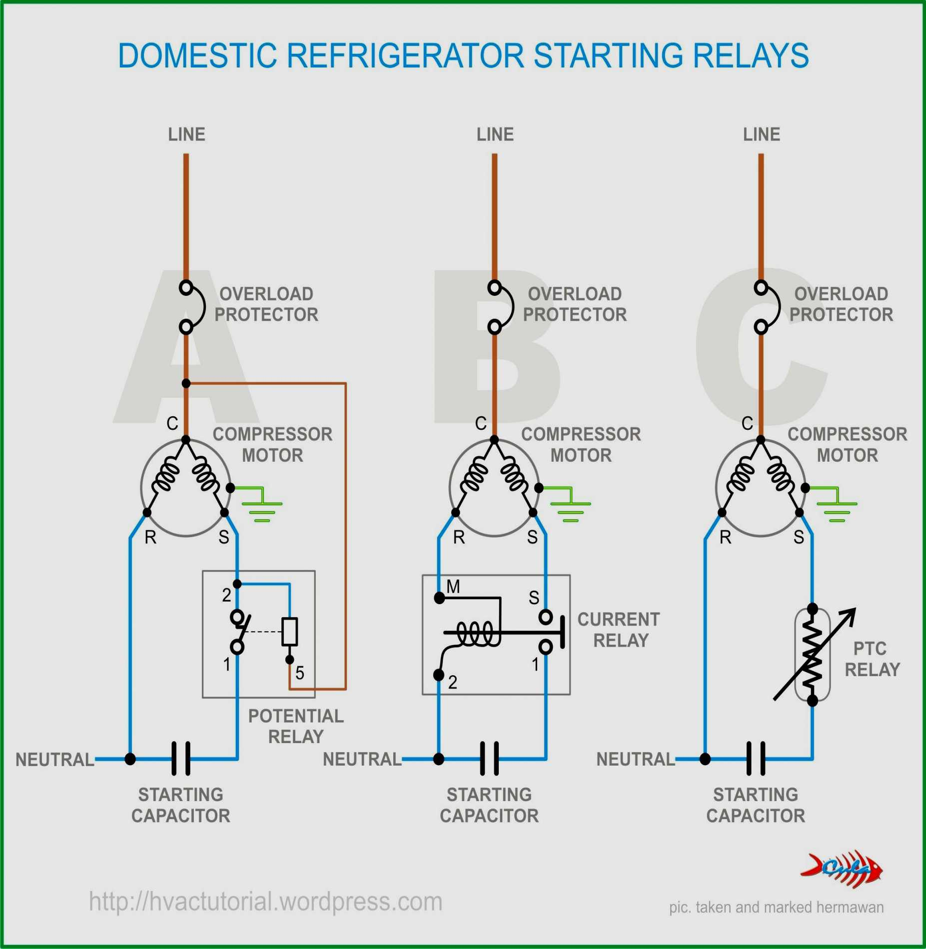 Single Phase Motor Wiring Diagrams 120 Volt
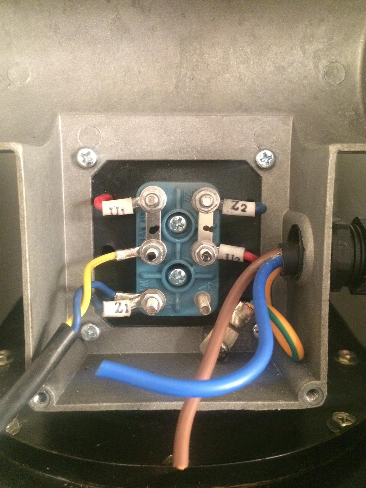 Wiring Diagrams Single Phase Electric Motor Earth Ground - Wiring
 Electric Motor Wiring Diagram Single Phase
 Single Phase Motor Wiring Diagram | EdrawMax | EdrawMax Templates
 Single Phase Motor Wiring Diagrams 230 Volt
