The wiring diagram a visual representation how fan be wired ensure proper operation safety. article provide with you to about exhaust fan wiring diagrams. Components an Exhaust Fan Wiring Diagram: Fan Motor: is main component powers fan circulates air .
 Read fan data label determine number phases amperage drawn the unit. Check the supply suitable. EARTHING fans be earthed accordance AS/NZS3000:2007 local supply regulations. WIRING Wiring be accordance AS/NZS3000:2007 local supply regulations.
 For other SINGLE-PHASE wiring diagrams refer the manufacturers data the motor. Diagram DD6 Diagram DD8 1~ LN Diagram DD9 1~ LN White Brown Blue L1 L2 S/C . CE35. over + fans shown Exhaust air mode. supply air mode bridge LA & LC not bridge LA & LB. Orange Blue 1~ 1~ L N E Brown Black LN LC .
 For other SINGLE-PHASE wiring diagrams refer the manufacturers data the motor. Diagram DD6 Diagram DD7 1~ LN Diagram DD8 LN L1 L2 L3 S/C Z1 U2 Z2 U1 Cap. Thermal contacts (TB) . CE45. over + fans shown Exhaust air mode. supply air mode bridge LC & LA Brown Orange Black Blue Blue 1~ 1~ L N E Brown .
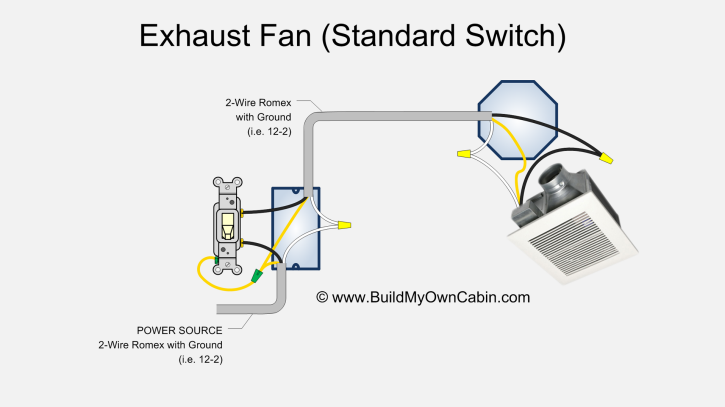 Diagram Wire Timer-Controlled Exhaust Fan. the exhaust fan controlled a timer of switch. should two hot wires, black red both same color, a green ground wire coming of timer casing, splice of hot wires the hot source. Splice second the black cable wire running the fan.
 A single phase exhaust fan operates a single alternating current (AC) power source, the voltage periodically switches direction. it to wiring diagram a single phase exhaust fan, typically consists three important components: fan motor, single-phase capacitor, the speed regulator.
 An exhaust fan schematic diagram provide diagrams the wiring components needed install fan. will explain step-by-step process setting the fan, including specifics the fan itself, space needs be installed in, the tools materials.
 Exhaust Fan Wiring Diagram Single Switch. 12v Dc Fan Motor Sd Controller Regulator Circuit Diagram. . Ruijp 220 240v 533 356 195mm Single Phase Asynchronous Exhaust Fan Motor China In Com. Automatic Bathroom Fan Controller Circuit. Fantech Fan Light Delay Timer Switch Fld 60.
 single phase type - 3 phase 3 phase 220/380v - 50hz 3 phase 230/400v - 50hz 3 phase 240/415v - 50hz . proposed temperature switch wiring diagram electric fans l1 l2 control voltage circuit purple red blue start fan motor high circuit set 140°f (60°c) brown yellow orange alarm main motor circuit
 CANARM SD FAN MODEL WIRING DIAGRAM S08-B2 / S10-B2 S12-E1 / S14-E1 / S16-E1 S12-E2 / S14-E2 / S16-E2 . Ire Sizes Three-Phase Motors 25 50 Feet 100 Feet 230V 14118)' 14118). 14116)' 14118). 150 200 Feet . fans supplied single, or variable speed motors. Single two speed motors 120V only.
 Master the Art of Wiring with Utilitech Fan: A Comprehensive Diagram Guide
 Reversible Exhaust Fan connection With Two way Switch | 3 wire Exhaust
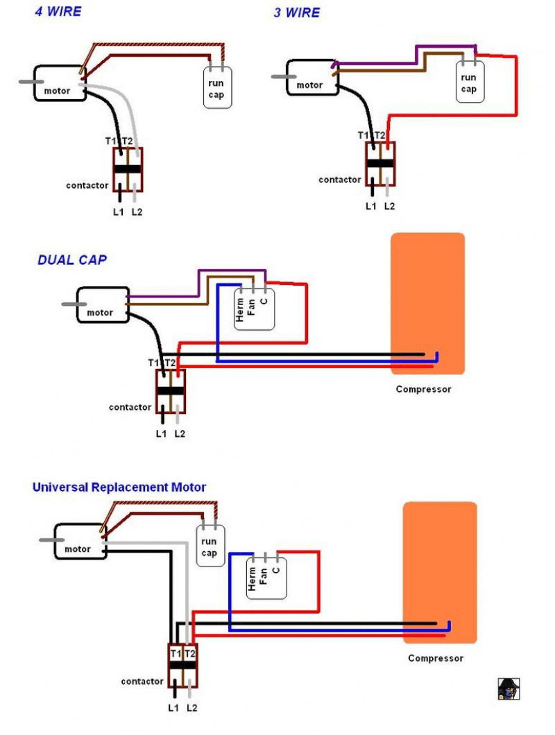 Industrial Exhaust Fan Wiring Diagram
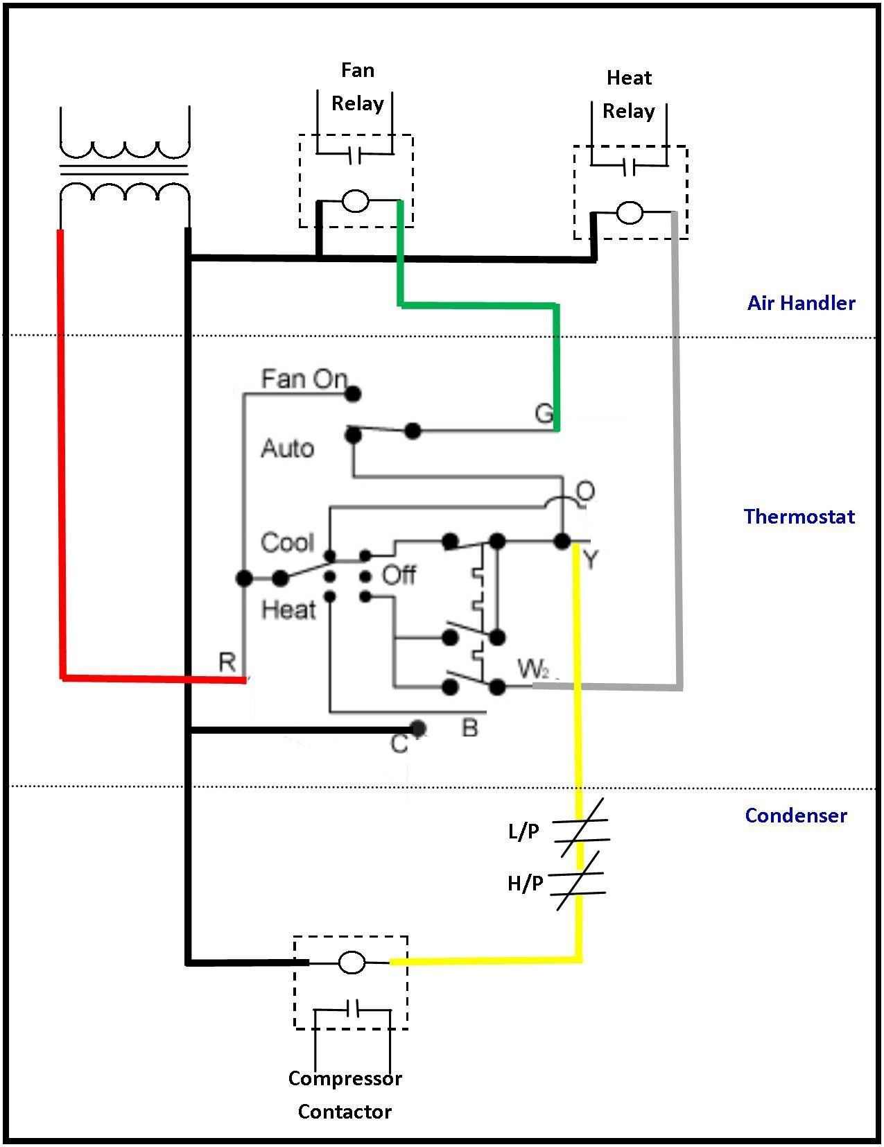 Wiring Diagram For Exhaust Fan
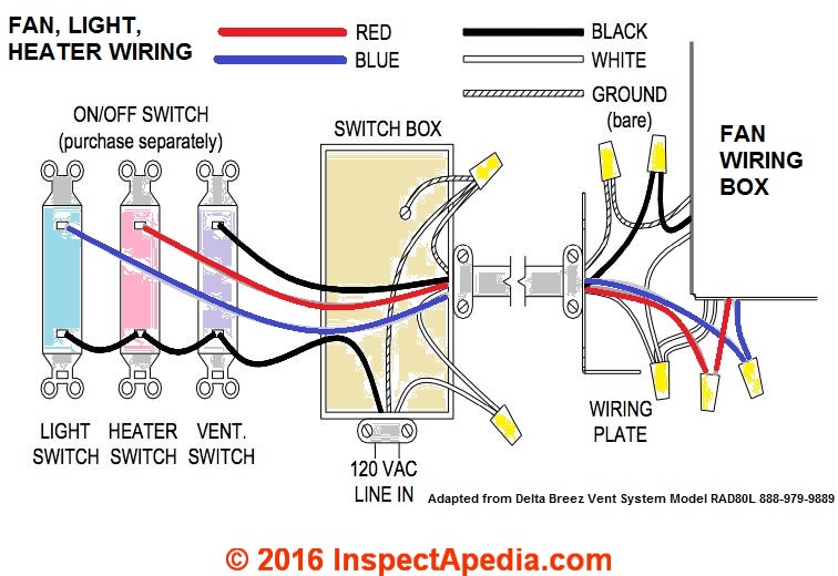
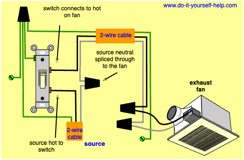 Bathroom Exhaust Fan Wiring Diagrams- Do-it-yourself-helpcom
 Exhaust Fan Internal Wiring Diagram
 How To Wire A Bathroom Exhaust Fan
![[DIAGRAM] Attic Fan Motor Wiring Diagrams Single Phase - MYDIAGRAMONLINE [DIAGRAM] Attic Fan Motor Wiring Diagrams Single Phase - MYDIAGRAMONLINE](https://www.electricaltechnology.org/wp-content/uploads/2019/11/wiring-diagram-of-split-phase-single-phase-induction-motor-in-a-ceiling-fan.png) [DIAGRAM] Attic Fan Motor Wiring Diagrams Single Phase - MYDIAGRAMONLINE
[DIAGRAM] Attic Fan Motor Wiring Diagrams Single Phase - MYDIAGRAMONLINE
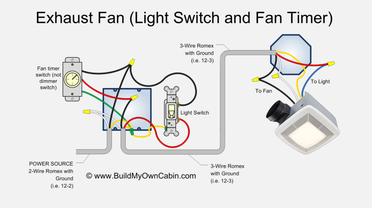
 Wiring Diagram Bathroom Light And Exhaust Fan
 How to Make Bathroom Light in Exhaust Fan Wiring Diagram | Exhaust fan
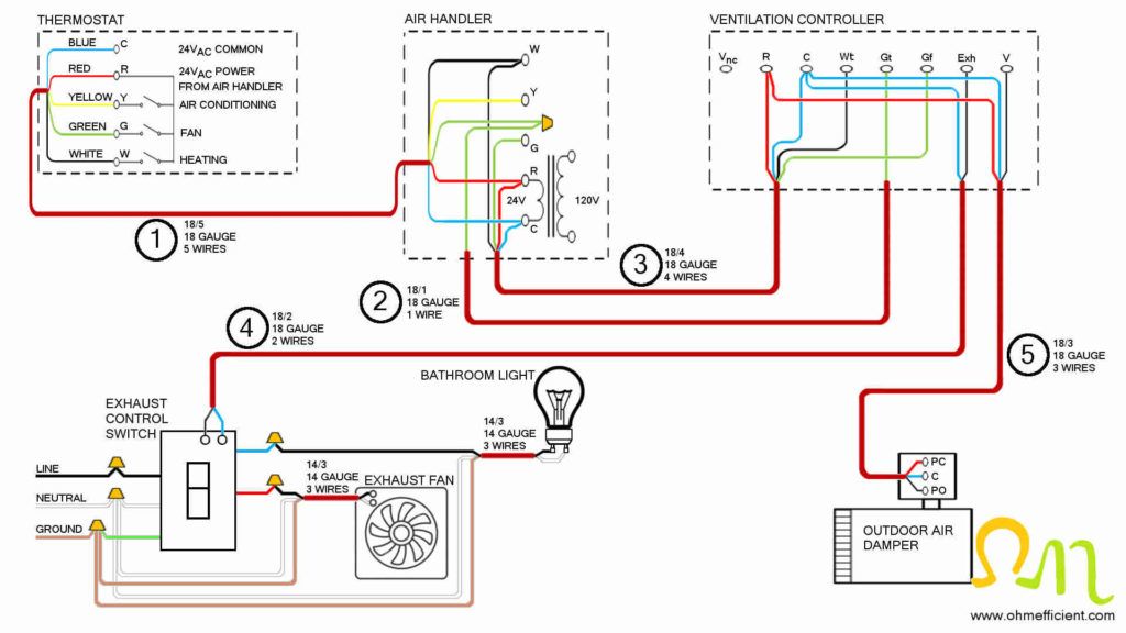 exhaust fan circuit diagram - Wiring Diagram and Schematics

