In summary, wiring diagram a three-phase water pump specify placement the hot conductors (L1 L2), well the ground conductor (G). is important follow diagram by manufacturer consult professional electrician ensure proper installation operation the pump.

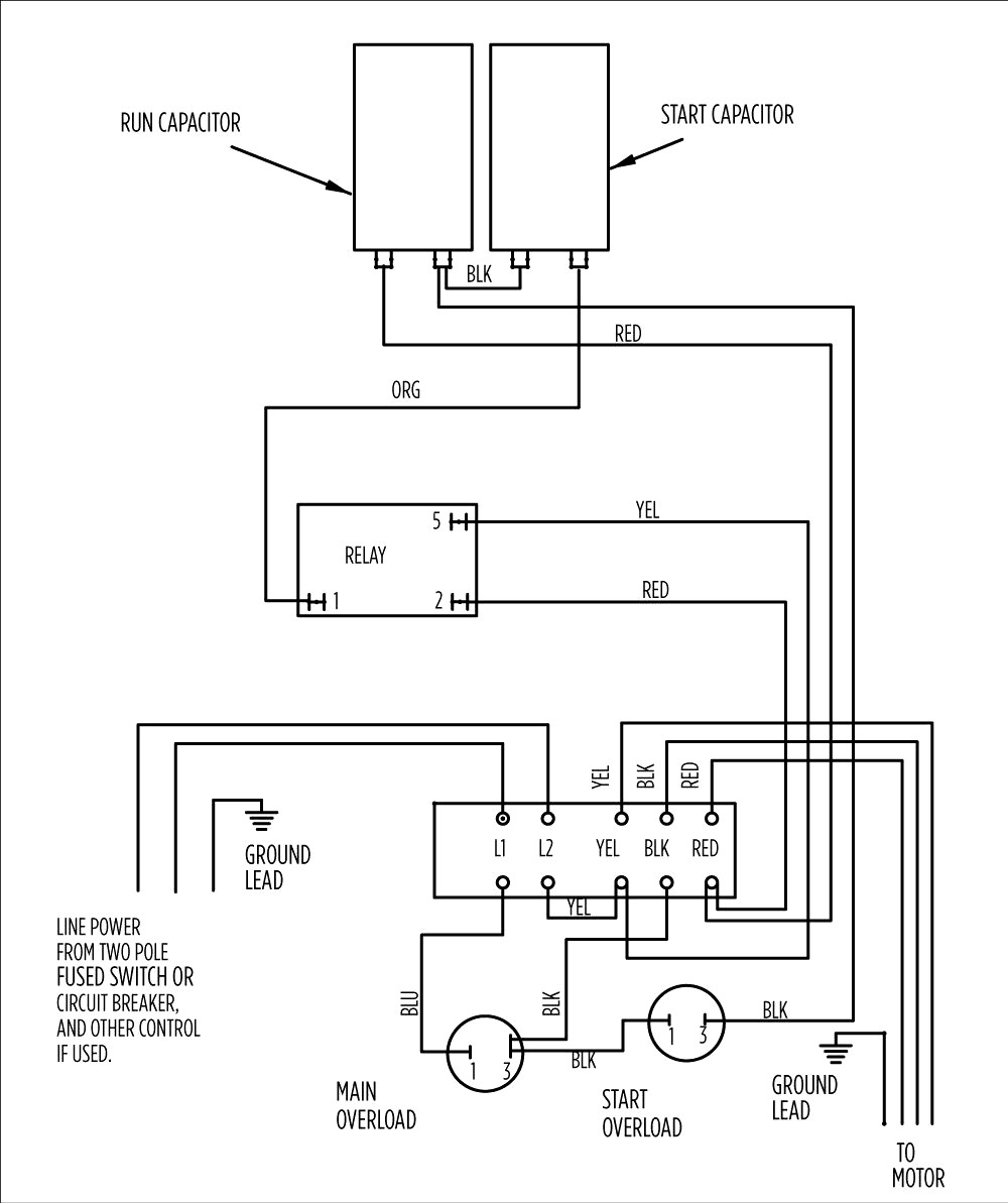
 Typical 3 4-wire submersible pump control box wiring diagram. 4-wire pump wiring connections typical a single-phase submersible pump. GREEN = ground; BLUE = run - will one the Line power wires; BROWN RED = start wire motor starting capacitor motor terminal shown above
 This video explained single phase submersible pump / motor control box wiring connection diagram. you any questions, comment th.
 Observe pump's functionality monitor any irregularities issues. everything working correctly, single phase submersible pump now successfully wired ready use. Determine Power Supply. wiring single-phase submersible pump, is important determine power supply will used.
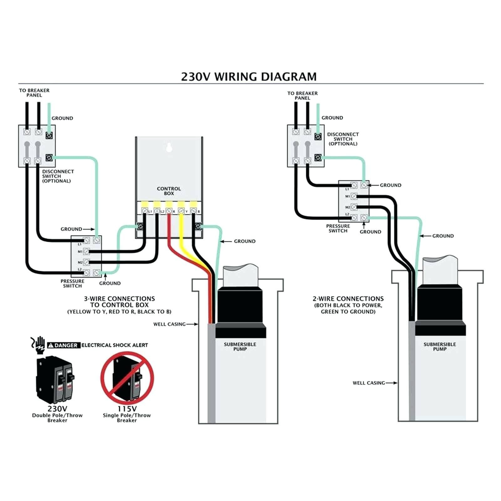
 Black wires to black wires, the green wire (the ground) to ground wire. Fig. 1 (Above): 2 Wire Pump Wiring Diagram . Three-Wire Pump Wiring Diagrams. 3-wire pump diagrams more complicated require better understanding electrical work. It's important the wire colors together. Fig. 2 (Above): 3 .
 Single Phase 1.1 2.2kW Schematic 0 Manual On/Off 22/09/2005 1 2 5 Run Capacitor Start Capacitor RELAY N YEL Main BLK . INTERNAL WIRING DIAGRAM 230VAC 50Hz 185VAC 265VAC 50Hz 195VAC 275VAC 50Hz . pump/motor unit. Voltage - Norminal Voltage - Operating Voltage - Starting Operating Temperature
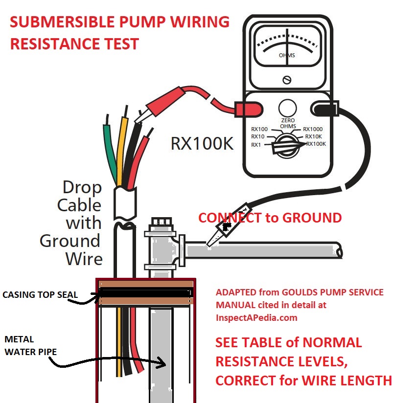
 Water Pump Wiring Troubleshooting Repair Diagrams. Brisan Standard Control Box 0 56kw 230v Pumps Africa. Automatic Control Box 220v 0 55kw Hurricane Pumps South Africa. China 220v Single Phase Submersible Pump Control Box Ce Certificate Water Controller Panel. Mac Afric 3 0 37 Kw Borehole Pump Complete Kit Control Box Wiring Adendorff .

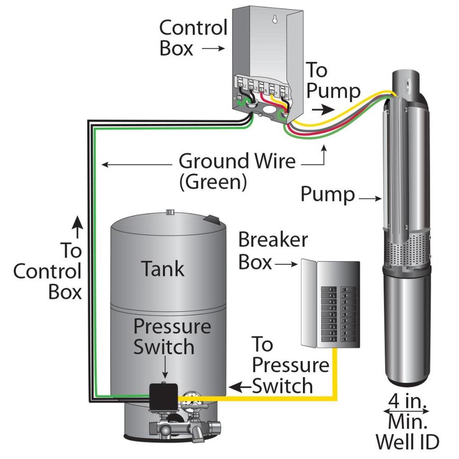
 A comprehensive diagram explaining process installing borehole pump. Learn the equipment steps involved setting a borehole pump system efficient reliable water supply. . Step-by-Step Guide: 2009 Dodge Caliber Wiring Diagram Explained; Detailed Guide the 2006 Ford F250 Trailer Wiring Diagram .
 Franklin borehole pump wiring
 Single Phase Submersible Pump Wiring Diagram - Earth Bondhon
 Submersible Pump Control Box Connection / Single Phase Submersible
 Float Switch Wiring Diagram For Water Pump Single Phase Floa
 Submersible Well Pump Motor Wiring Diagram
 Vevor Submersible Well Pump Wiring Diagram Submersible Well
 Submersible Well Pump Wire And Connectors
 Water Pump Wiring Diagram Single Phase
 How To Wire A 240 Volt Submersible Well Pump

 Wiring Submersible Well Pump
