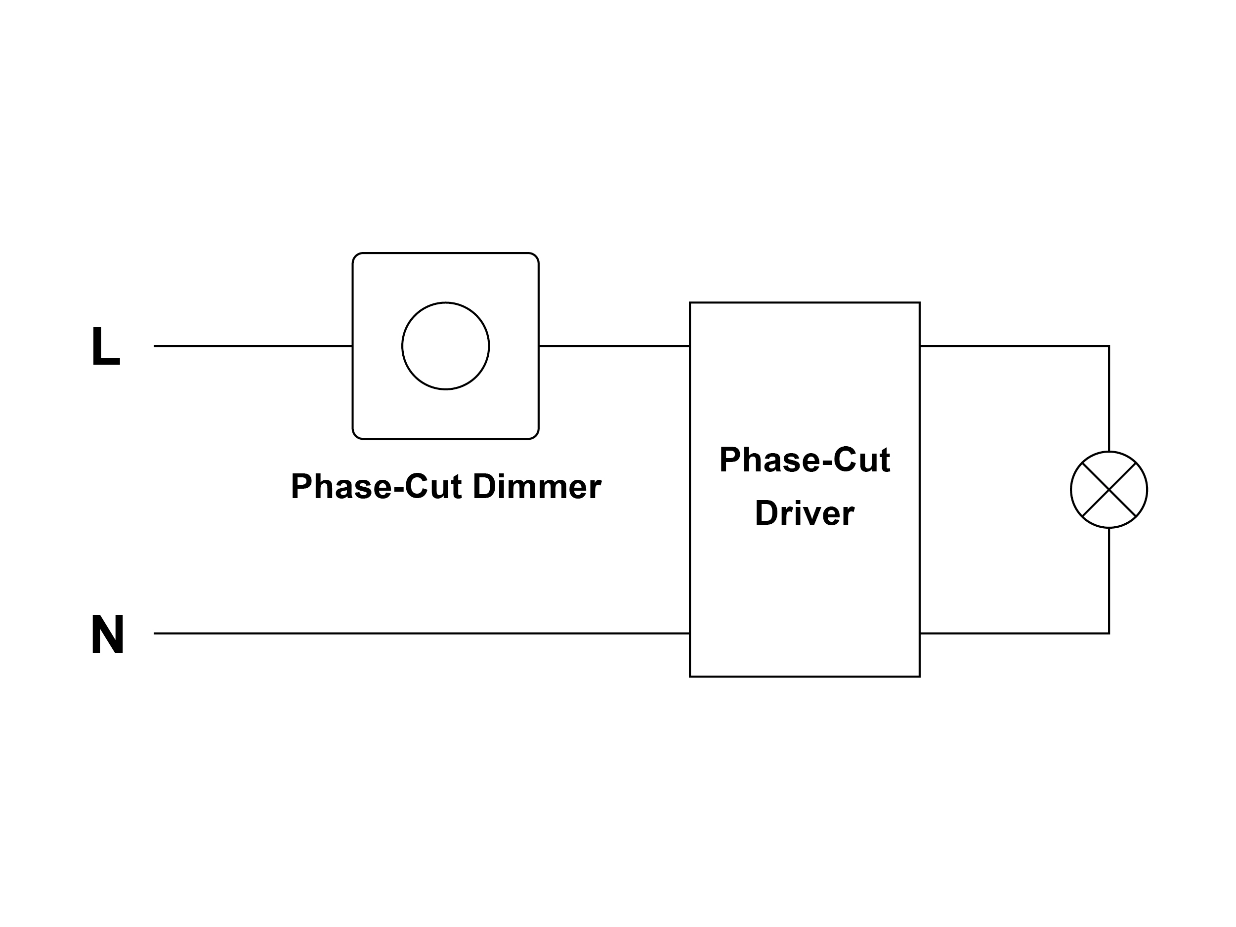
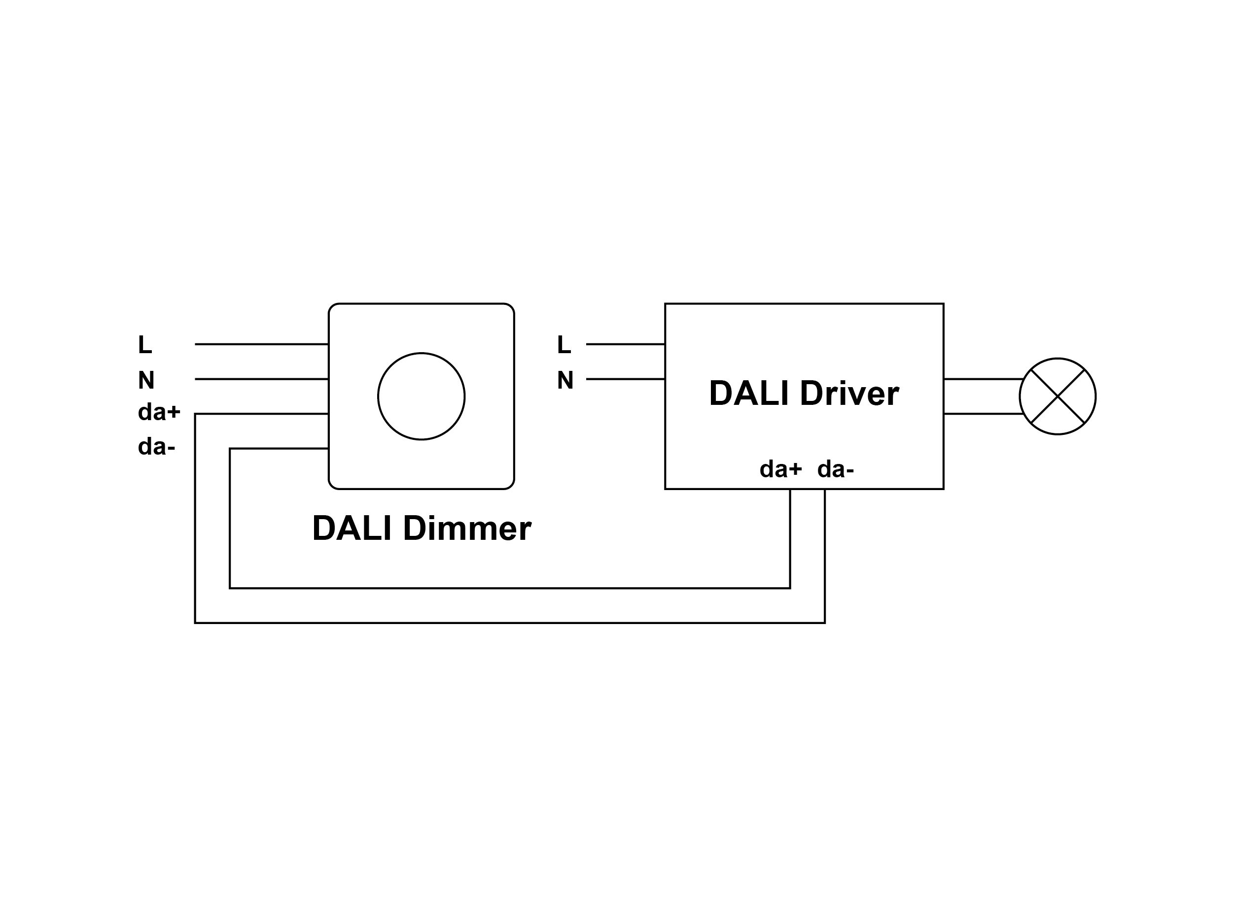
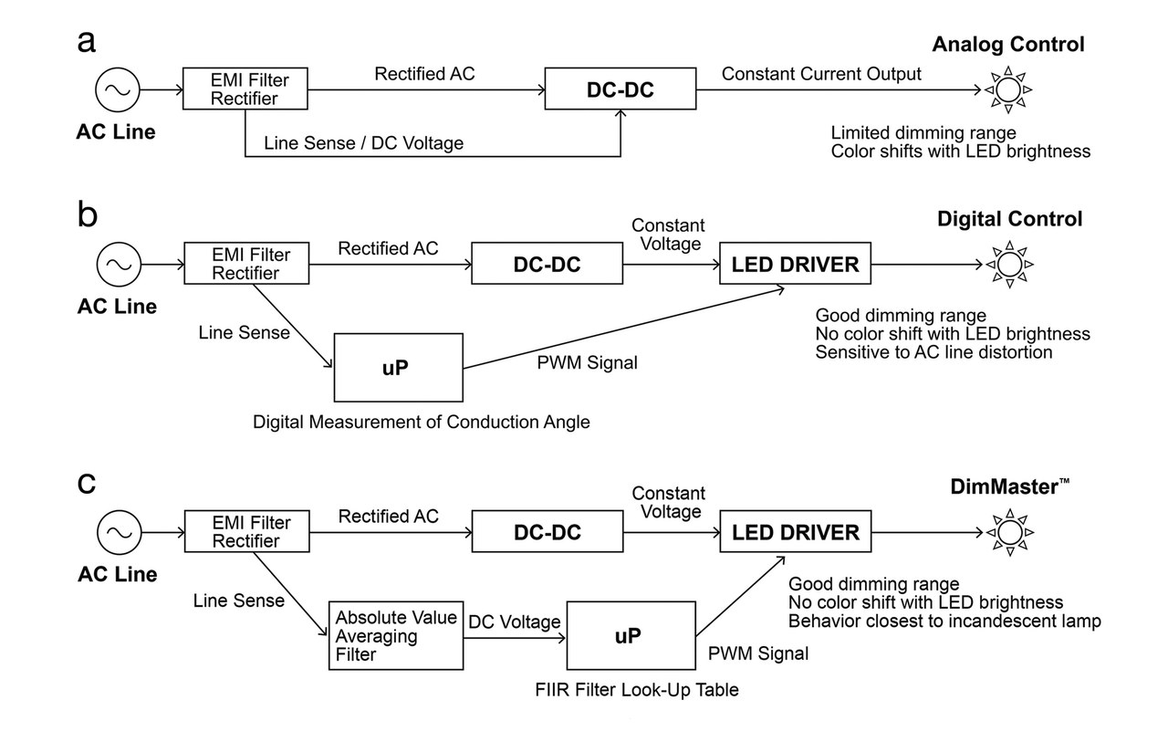
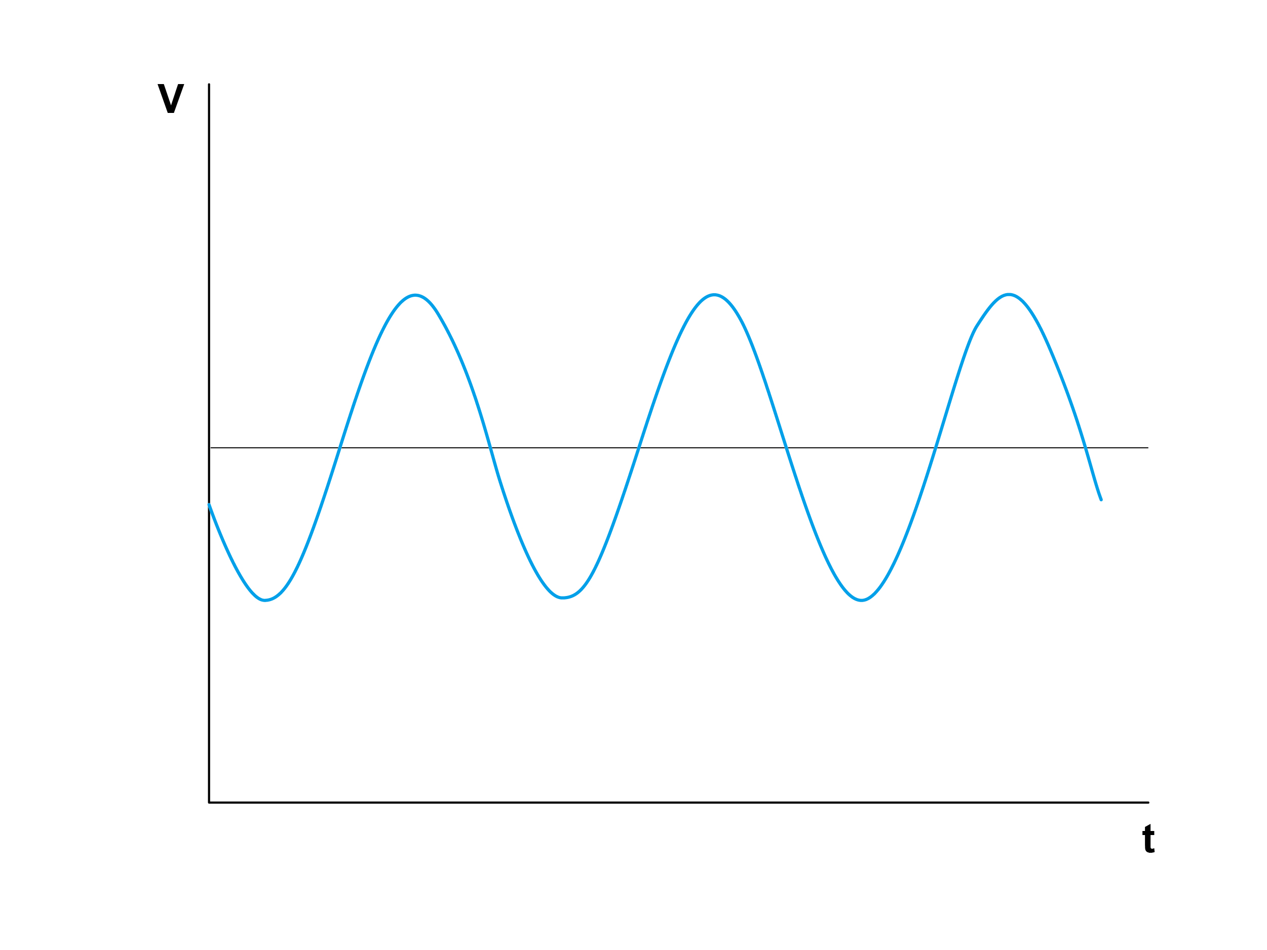
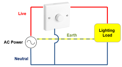
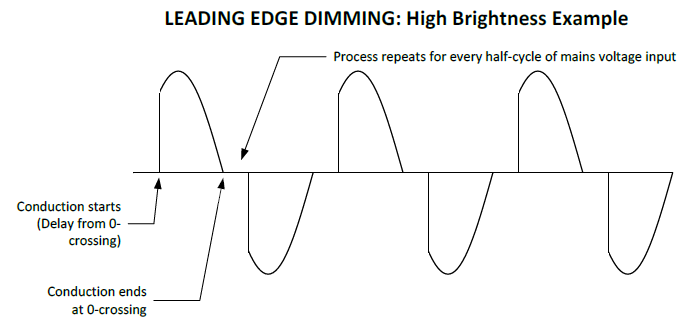
Phase cut dimming be categorized leading edge (forward phase) trailing edge (reverse phase) mode. Let's talk the difference two phase cut dimming types. . Diagram (2) the wiring diagram DALI system. Compared phase-cut wiring system, DALI system require extra control lines function. the .
 "Phase Dimming" actually umbrella term encompasses different, related, dimming methodologies. first phase dimmer be developed the Incandescent Forward Phase dimmer. was by Electronic Voltage dimmer Reverse Phase dimmer addressed of key problems Forward .
 LUTRON PHASE DIMMING DRIVER WIRING DIAGRAM Product Code T: LUTRON Phase Dimmable the product spec sheet *DRIVER SWITCH ILLUSTRATED FOR PURPOSES - MANUFACTURERS VARY DEPENDING TECHNICAL REQUIREMENTS THE LIGHT* Red Black Line Neutral GND LUTRON™ Phase Dimming Control Neutral Line Blue Brown
 In article, we'll walk through steps wire LED dimmer, complete a diagram better understanding. Types LED Dimmers. diving the wiring process, it's important understand types LED dimmers available: Phase-Cut Dimmers: Suitable residential applications, are most common types .
 Phase Cut Dimming Module Wiring installation manual Overview PCDM an interface the dimmable reverse phase ballasts LED drivers osram dam 2309834 LMS157R2 Dimmer Installation Manual media info im img . Untitled PCDM Wired Wiring Diagram encelium 2021 05 .
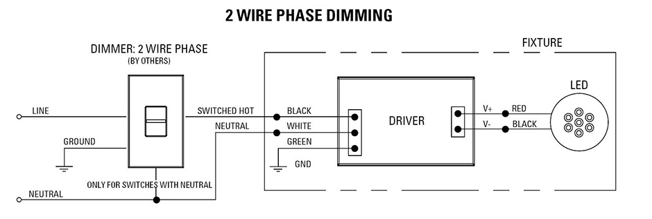
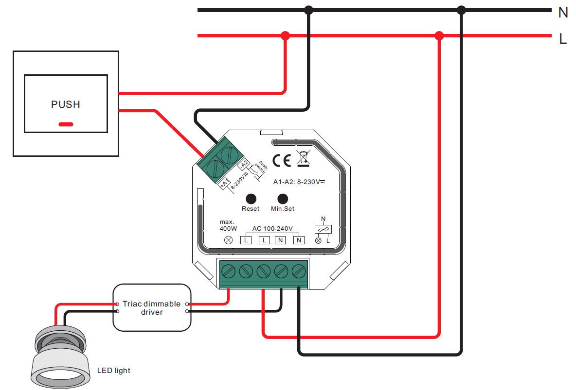 • 2-wire phase dimmers not used ELV (electronic low-voltage) drivers doing could any the malfunctions: dimmer buzz, lamp flicker, interaction circuits radio frequency interference (RFI). Triac Dimmer Wiring Diagram: Dimming Control Information 0-10V (4 wire, Voltage) Dimming: .
 3. the applicable wiring diagram in Figure 1, connect desired lighting load be controlled the side the device labeled LOAD. Ensure connect wires Line (Black), Neutral (White), Ground (Green) the flexible conduit. FIGURE 1: Wiring Diagram Room Controller 4.
 Wiring diagram • 1 DALI address control 1 channel output, to 400W • Input output screw terminals, safe reliable . • 100-240VAC wide input output voltage, • AC phase cut dimmer both DALI push switch control interface • Match DALI systems the market • Built-in DALI-2 interface, DALI DT6 device .
 Wiring diagram • compliance IEC 62386-101:2014, IEC 62386-102:2014, IEC 62386-207 Ed2. • Built-in DALI-2 interface, DALI DT6 device • Match DALI systems the market • AC phase cut dimmer both DALI push switch control interface • 100-240VAC Wide Input Output Voltage, • 1 DALI address control 1 Channel .
 DALI/DMX - Phase-cut Dimming Module Main Characteristics Wiring Diagram 改端子,加拨码开关 100~240Vac 5A LT-834 DMX/RDM DALI, PUSH DALI L N L L DMX/RDM www.ltech-led.com Update Time: 2018.10.18_A2 Unit:mm 175 170 44 30 Dimensions DALI Connection DMX/RDM Connection Push Connection DIM 0~100% Dimming 0~100% Dimming PUSH DIM
 Dimming AC Mains Phase Dimming - Ansell Lighting
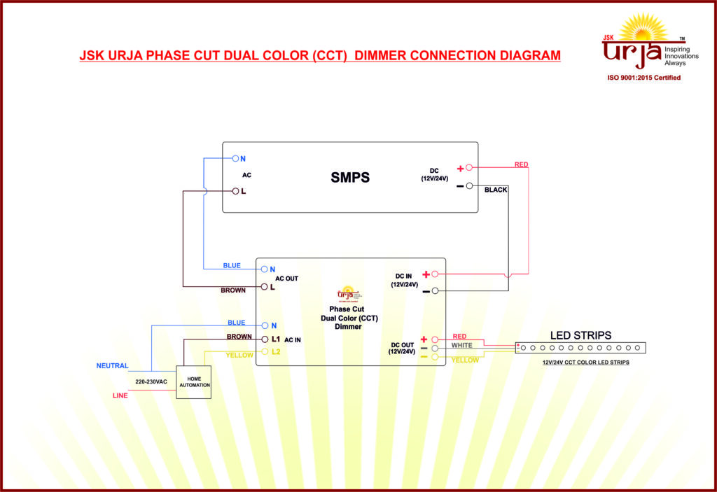 CCT Phasecut Dimmable Dimmer - JSK INNOVATIVE TECHNOLOGY PVT LTD
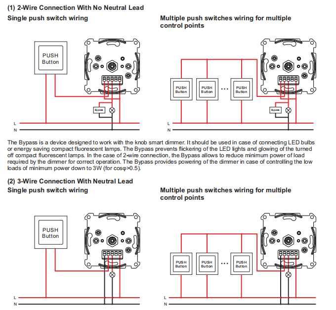 ZigBee & Rotary Manual Control Wall Mounted AC Phase-Cut Dimmer SR
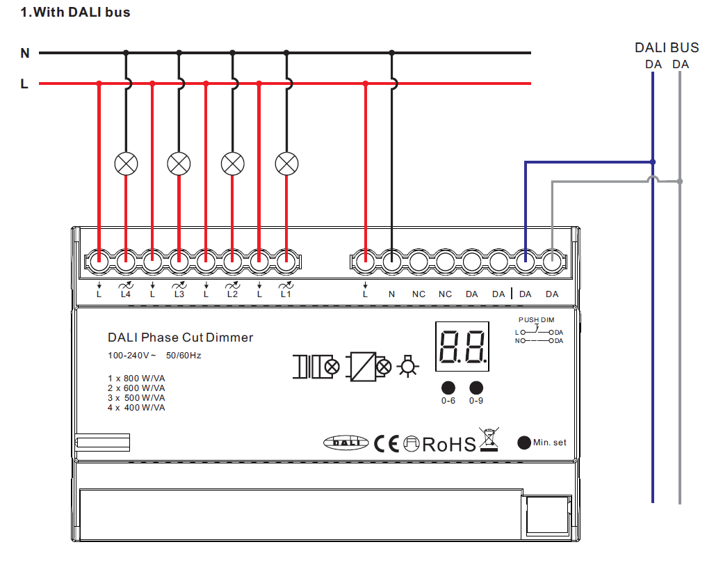 4 Channels DALI Phase Dimmer 70040042 SR-2303AC-4CH-DIN - LED DOMAIN
 Phase Dimming Wiring Diagram - Enhandmade
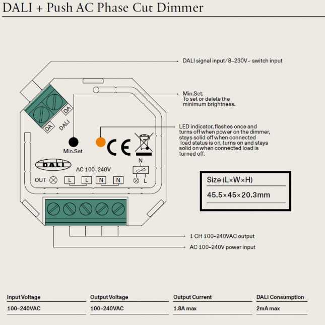 DALI + PUSH AC PHASE CUT DIMMER BY LODES

 Tutorial: Phase Dimming - Ozuno
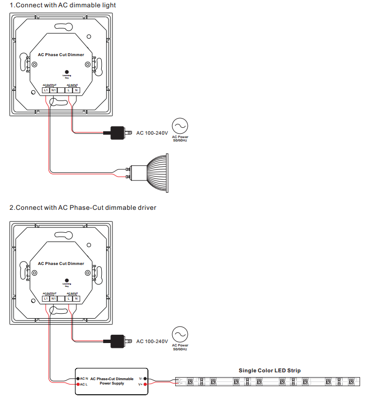 RF & Rotary Manual Control AC Phase-Cut Dimmer SR-2400TAC-RF
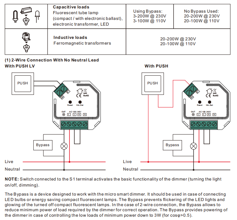 ZigBee Mini AC Triac Phase-Cut Dimmer Single Live Wire with Power
 Clipsal Led Dimmer Wiring Diagram - Circuit Diagram
