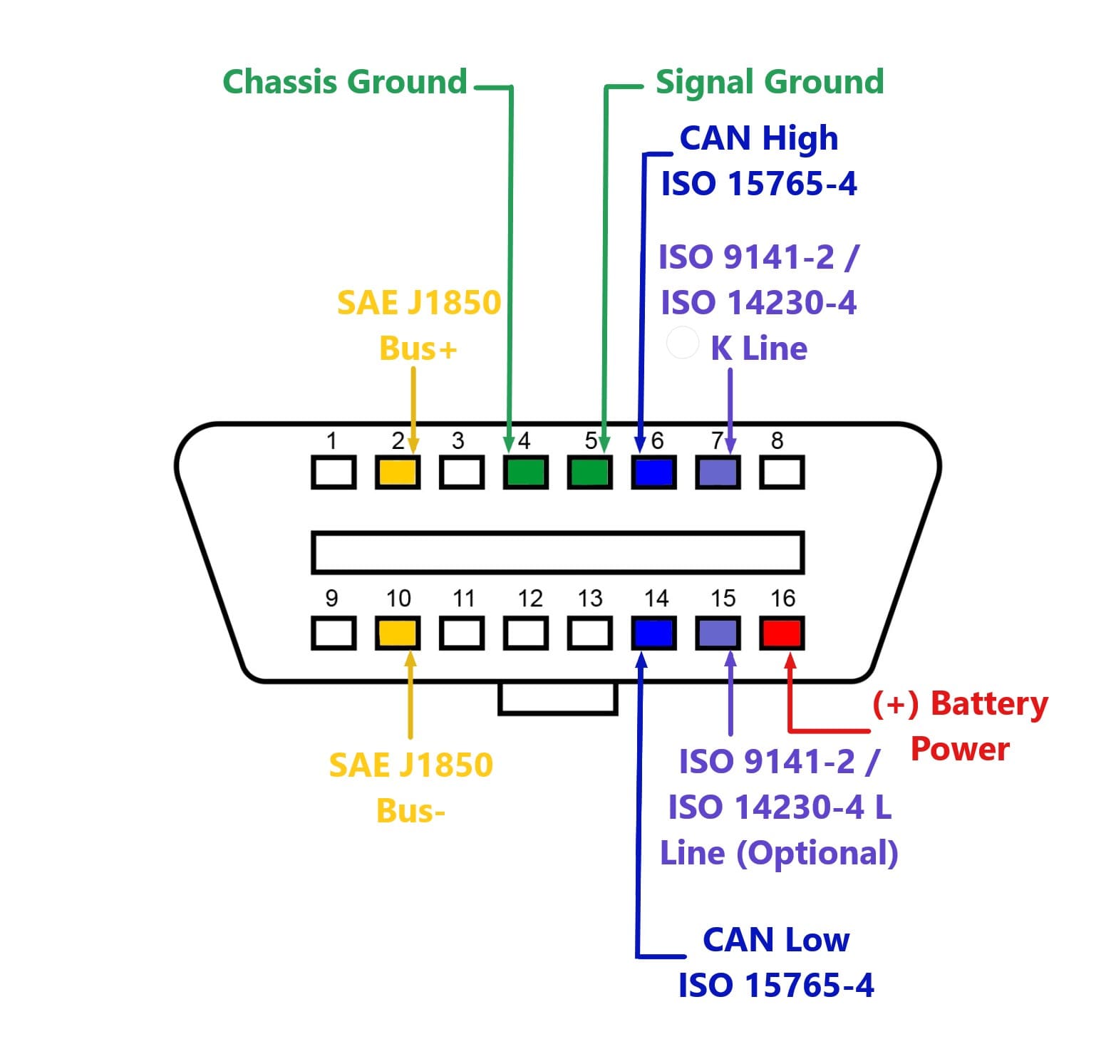
Pinout Volkswagen OBD II diagnostic connectorapplied some 1994-1996 all after-1996 models. Pinouts / Devices / Connectors. . J1850 Bus-Not used? 14: Low: ISO 15765-4 SAE J2284: 15: ISO 9141-2 L-LINE: ISO 9141-2 ISO/DIS 14230-4 used? 16 +12v: Battery power .
 Key diagram Turn signals highlight Wiring Cheat Sheet (1973-75) 1973 : 1700cc Key diagram: 1973-74: Merged version Symbols sheet Alternator wiring Wiring Cheat Sheet (1973-75) 1974-75: Merged version Interior Lighting Fuel Injection Headlight washer Wiper Delay Front rear fog light wiper/delay Wiring Cheat Sheet (1973-75) 1976 .
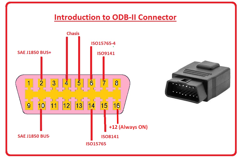 OBD 2 Pinout Explained On-Board Diagnostics II, OBD2, a self-diagnostic reporting system modern vehicles. consists an Electronic Control Unit, sensors, indicator lights. . LS Bus for speed bus, called multimedia bus: 13: . Volkswagen OBD2 connector pinout Pin Number: Description: 1 .
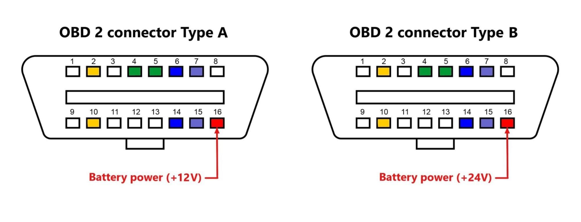
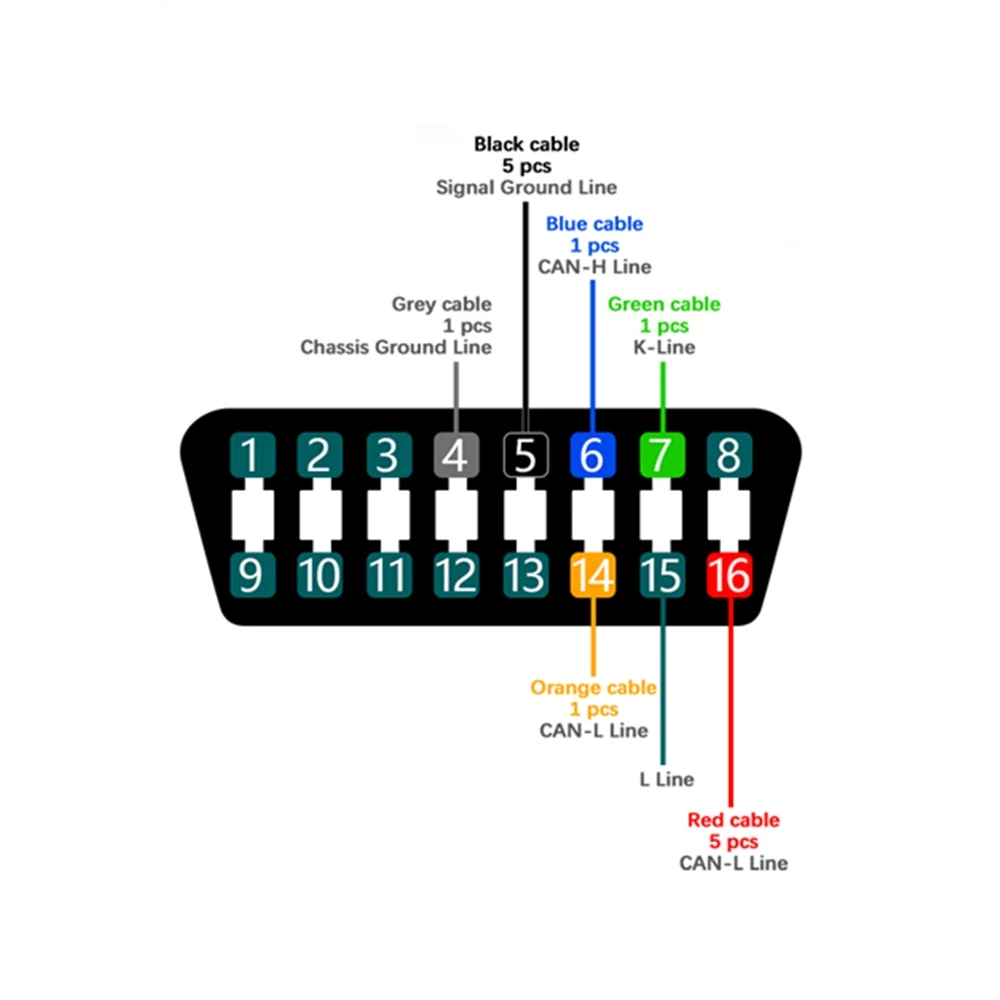
 OBD-2 connector have pins 4, 5 ground connections pin 16 power supply the vehicle battery. . OBD-II bus. bus in Ford, Mazda, Volvo most cars 2004. CAN protocol a popular standard of automotive industry is making significant in-roads the OBD-II market share .
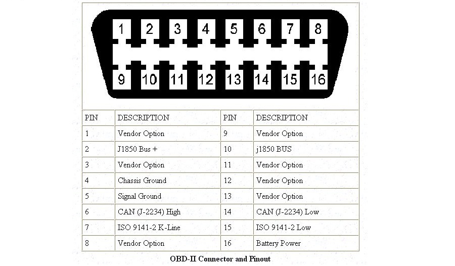
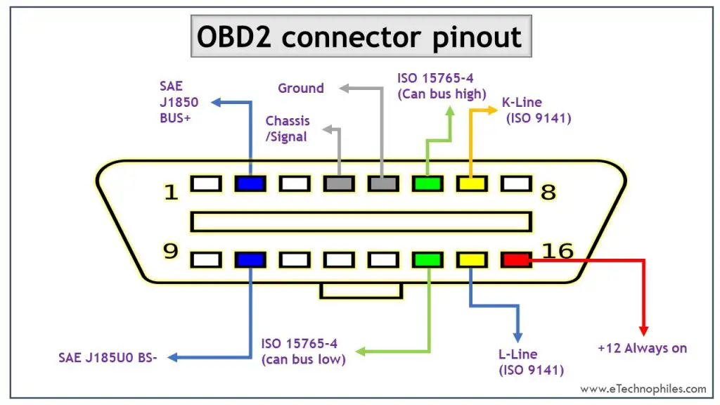 An OBD2 wiring schematic a diagram illustrates electrical connections pin assignments the components an OBD2 diagnostic connector. provides visual representation how wires connected the connector. . Pin 2 used SAE J1850 bus communication, pin 4 used chassis ground, pin 5 used .
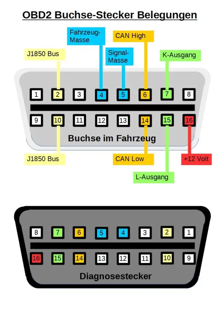 If are pins 2 10 the connector, metallic pins 2, 4, 5, 10 16 the vehicle using SAE J1850 PWM protocol.; you see pin 2 material contacts pins 2, 4, 5, 16 there's pin 10 the vehicle using SAE J1850 VPW protocol.; the connector pin 7 maybe pin 15 the vehicle be either ISO 9141-2 ISO .
 OBD-II BMW Chrysler Ford GM Honda/Acura Hyundai/Kia Mazda Mercedes Benz Mitsubishi Nissan/Infinity Subaru Toyota/Lexus VW/Audi Volvo. . Manufacturer Discretionary: 2: SAE J1850 Bus + (VPW / PWM) 3: Manufacturer Discretionary: 4: Chassis Ground: 5: Signal Ground: 6: High (ISO 15765-4 SAE J2284) 7: ISO 9141-2 / ISO 14230-4 Line: 8:
 Volkswagen > Beetle > 1998 - 2005 . Instrument cluster not disassembled. Troubleshooting specific systems circuits => Electrical Wiring Diagrams Troubleshooting & Component Locations Additional information . Board Diagnostic (OBD) Data Lo-Bus 29 - Open 30 - Output signal 2 electronic speedometer (where applicable
 To finish run-on period, data bus diagno-sis interface initiates sleep command. data bus diagnosis interface S307_047 J533 J104 J220 J217 Drive train data bus Term. 30 Internally switched terminal 15 data bus diagnosis interface J533 manages master functions terminal 15 run-on the drive
![OBD2 pinout of GM, Ford, BMW, Honda, Nissan [Updated list] - OBD Planet OBD2 pinout of GM, Ford, BMW, Honda, Nissan [Updated list] - OBD Planet](https://obdplanet.com/wp-content/uploads/2021/10/obd2-protocols.jpg) Re: wiring diagram obd2 port. (-EURO-) Aw yeah. fun begins. doesn't straight the ECU, goes a data bus the dash. the fuse panel, will find bundle wires. majority this bundle be light-gauge white grey wires. K L lines the OBD connector into bundle.
Re: wiring diagram obd2 port. (-EURO-) Aw yeah. fun begins. doesn't straight the ECU, goes a data bus the dash. the fuse panel, will find bundle wires. majority this bundle be light-gauge white grey wires. K L lines the OBD connector into bundle.
 OBD2 Connector Pinout, Types & Codes | Obd, Obd2, Electrical circuit
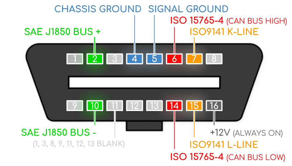 Diagram Obd2 Connector Wire Colors
 OBD-II CAN-BUS Development Kit - Longan Docs
 OBD2 Connector Pinout, Types Codes(Explained), 59% OFF
 OBD2 Connector Pinout, Details Datasheet, 50% OFF
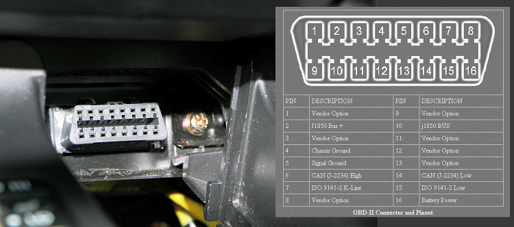 Obd2 Wiring
 Diagram Obd2 Connector Wire Colors
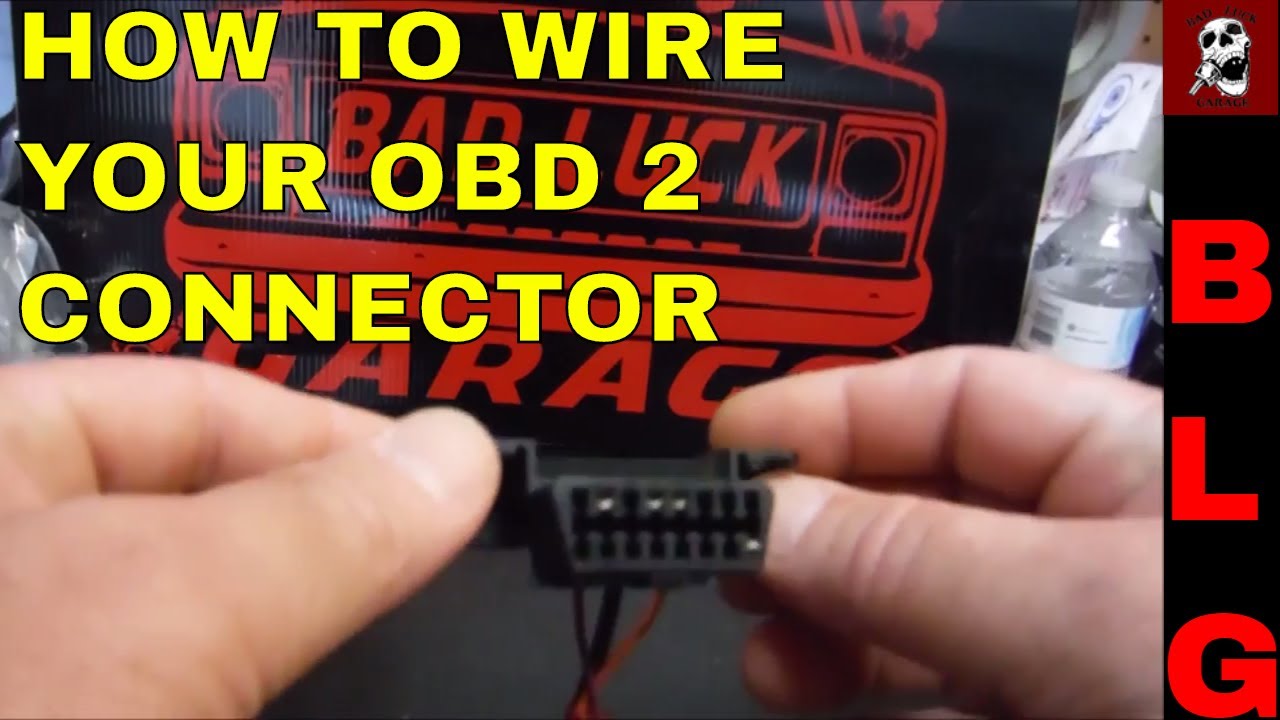 Obd2 Connector Wiring Diagram
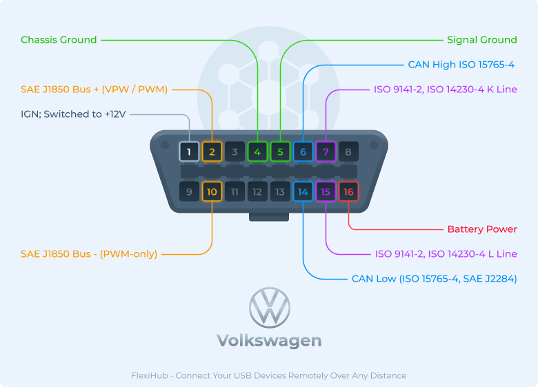 OBD2 Pinout Major Car Brands Pinouts, 48% OFF

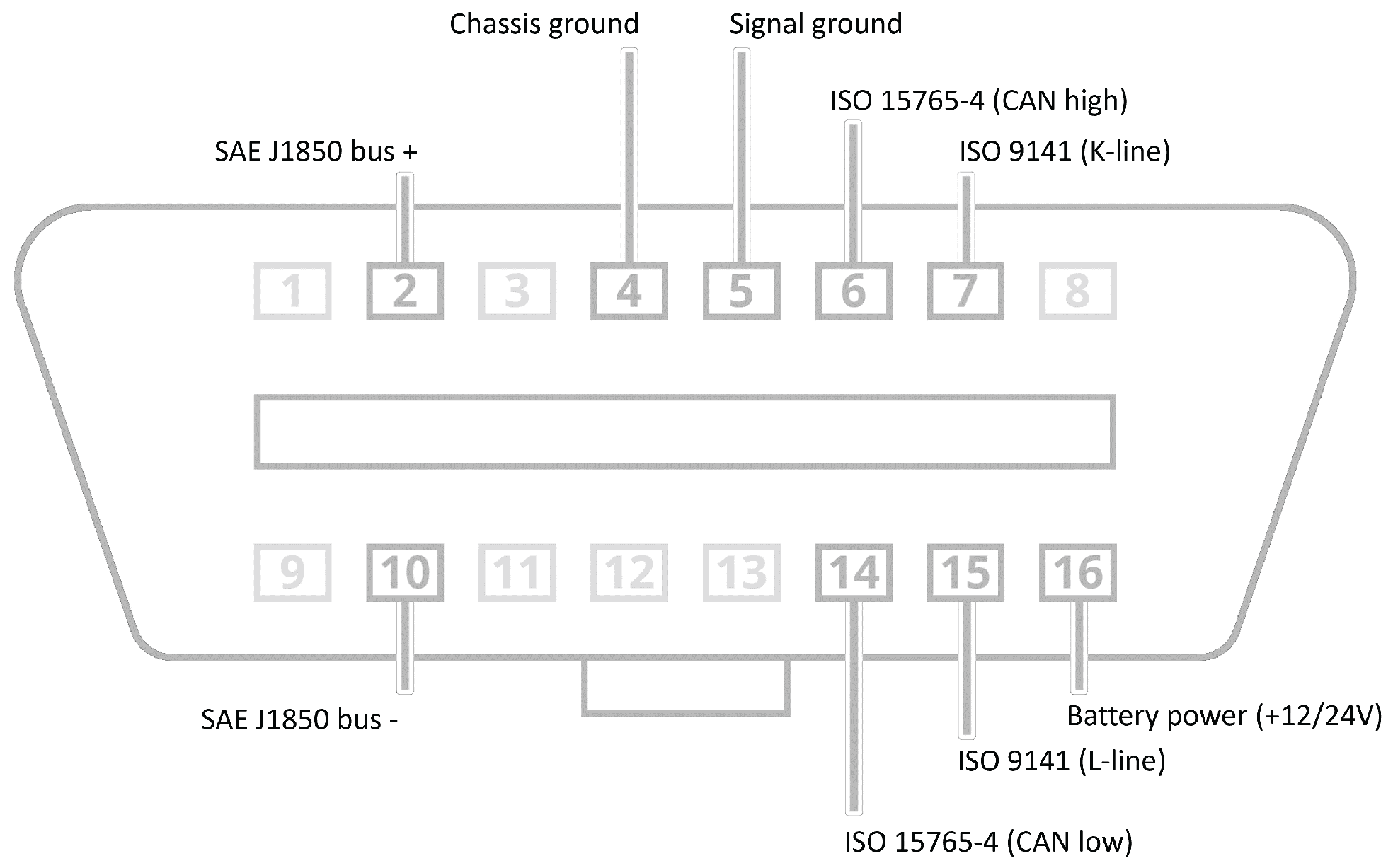 Framework for Building Low-Cost OBD-II Data-Logging Systems for Battery
