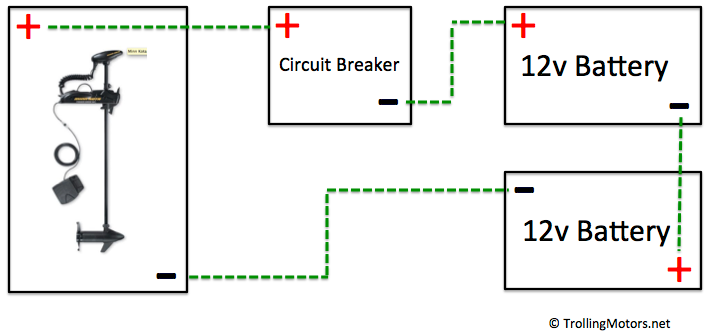
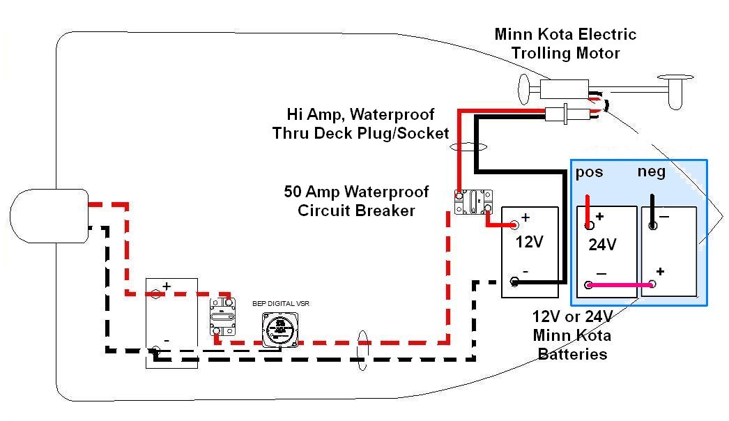
Stay connected Minn Kota. Sign here, we'll drop a line. TROLLING MOTOR WIRING DIAGRAMS . Trolling Motor Plug *Optional - MKR-28 (1865120) 12 Volt Battery; Circuit Breaker - MKR-27 (1865115) . 24 VOLT TROLLING MOTOR WIRING DIAGRAM following schematic outlines necessary accessories/cables needed connect trolling .
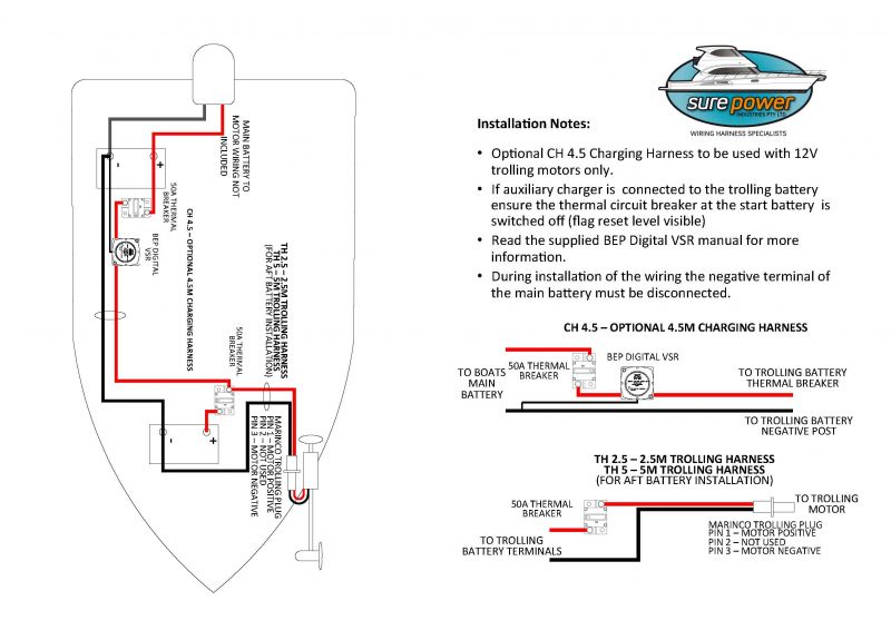 trolling motor install & rigging diagrams Diagrams outlining accessories cables required connect trolling motor a 12v, 24v, 36v, 48v system. TROLLING MOTOR INSTALL/WIRING DIAGRAMS
 Minnkota Autopilot 24 Volt Plug Wiring Diagram
 1998 Minn Kota AutoPilot 824 . Wiring Diagram . Diagram # Product Info 1 HSG BRUSH - 421-065 2 BRUSH PLATE HOLDER - 738-036 3 SPRING - TORSION - 975-040 . 78 CONNECTOR CABLE-(24 VOLT) - 2090620 79 WIRE INSULATOR-LGE 1-3/4 - 2065400 80 FOOT PEDAL ASSY-(765T) - 2774700
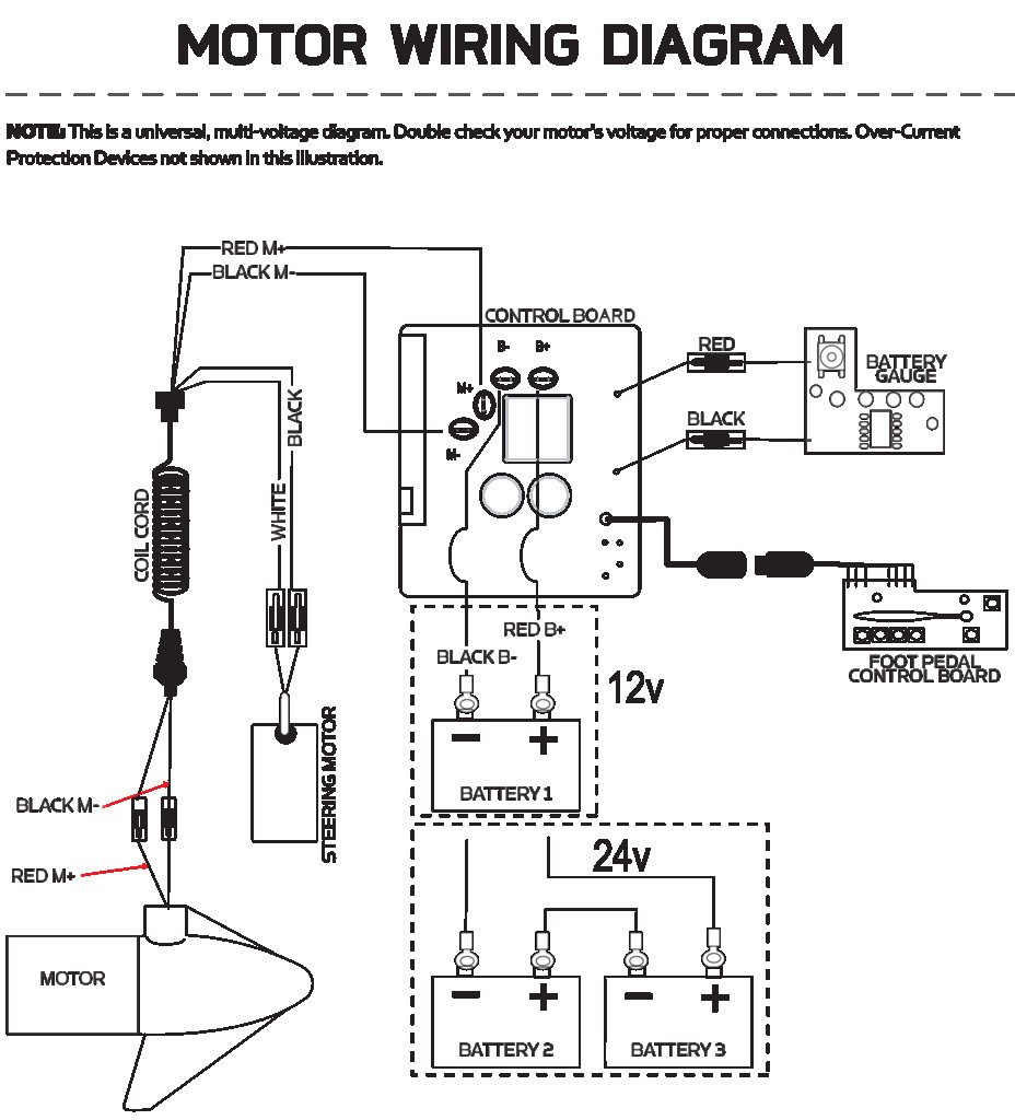 24 Volt Systems (2 Batteries) 12-volt batteries required. batteries be wired series, as directed the wiring diagram, provide 24 volts. sure the motor switched (speed selector "0"). Connect connector cable the positive ( + ) terminal battery 1 to negative ( - ) terminal .
 1999 Minn Kota Auto Pilot 62 . Wiring Diagram . Diagram # Product Info 1 Minn Kota Trolling Motor Part Available 2 THRUST DISC - METAL . 80 CONNECTOR CABLE-(24 VOLT) - 2090620 81 WIRE INSULATOR-LGE 1-3/4 - 2065400 82 FOOT PEDAL ASSY-(765T) - 2774700 83 FOOT PEDAL BASE - 2304511
 The wiring diagram a Minn Kota 24 volt trolling motor typically includes details the battery configuration, motor's positive negative terminals, well the connections the control panel. . modern trolling motors equipped technologies GPS, autopilot, wireless remote control, allowing anglers .
 70 lbs thru˜ - 24 volt - 54"/60" sha˚ item qty part number description. 1 1 2-100-119 armature ˚ sy 24v 2 1 140-010 ball bearing 3 1 788-015 r˛ aining ring 4 1 2-200-005 housing ˚ sy center 5 1 421-065 housing -brush 1 9421-168 housing - brush us2 6 1 2-400-101 p˝ end housing ˚ sembly 3.625 7 1 144-049 bearing - f˝ nge
 Additional wires: Minn Kota motors have additional wires features sonar autopilot. wiring diagram indicate these wires be connected ensure proper functionality. a Minn Kota plug wiring diagram hand save time prevent mistakes the installation troubleshooting process. .
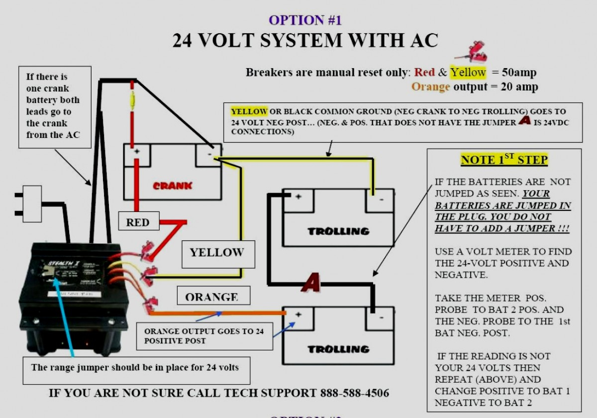
 The 24 Volt Minn Kota wiring diagram a diagram shows the wiring be configured connect trolling motor the battery. is important component the installation process provides visual representation how pieces fit together. diagram include information as wire size, type .
 Understanding Wiring Diagram. wiring diagram the Minn Kota 24 Volt system fairly straightforward. most important to remember that two batteries be wired series. means the positive terminal one battery connected the negative terminal the other. is creates 24 Volt system.
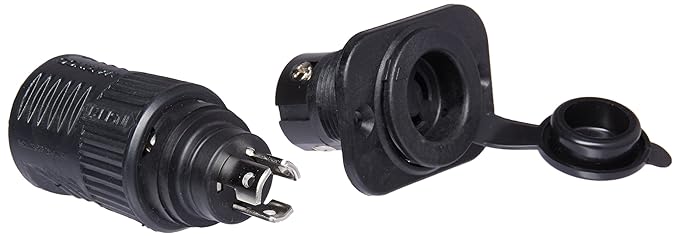 Minnkota Autopilot 24 Volt Plug Wiring Diagram - Wiring Diagram Pictures
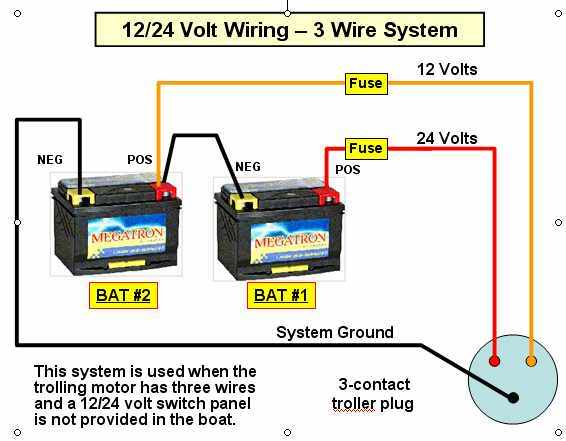 Minn Kota 24v Wiring Diagram Minn Kota Battery Charger Wirin
 Minnkota Autopilot 24 Volt Plug Wiring Diagram
 Minn Kota Wiring Guide
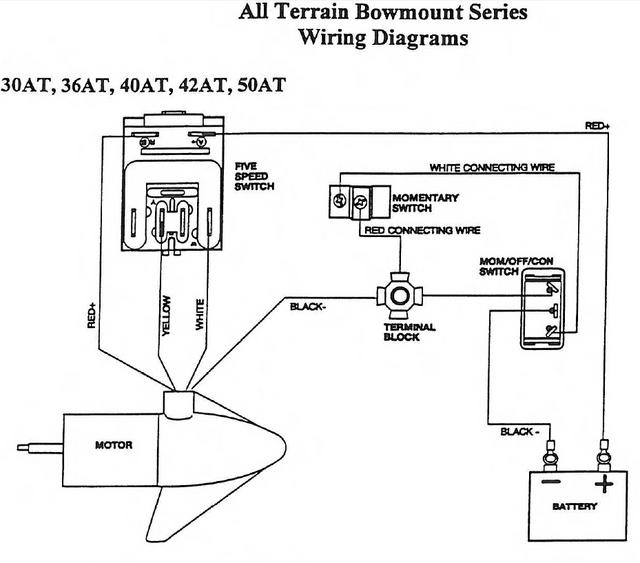 Minn Kota Wiring Chart
 Minn Kota 24 Volt Trolling Motor Wiring Diagram
 The Complete Guide to Wiring a Minn Kota Autopilot: Step-by-Step
![[DIAGRAM] Minn Kota 24v Wiring Diagram Plug - MYDIAGRAMONLINE [DIAGRAM] Minn Kota 24v Wiring Diagram Plug - MYDIAGRAMONLINE](https://cimg3.ibsrv.net/gimg/www.thehulltruth.com-vbulletin/2000x1504/2255c9f4_c64e_4457_86e0_1e72bc7a2d70_144623acfae1bedb9daf8b036fa693ffb816bd9d.jpeg) [DIAGRAM] Minn Kota 24v Wiring Diagram Plug - MYDIAGRAMONLINE
[DIAGRAM] Minn Kota 24v Wiring Diagram Plug - MYDIAGRAMONLINE
 Minn Kota 24 Volt 80 Lb Thrust
 Wiring A Minn Kota 24 Volt Trolling Motor
