Find parts & diagrams your John Deere equipment. Search parts catalog, order parts online contact John Deere dealer.

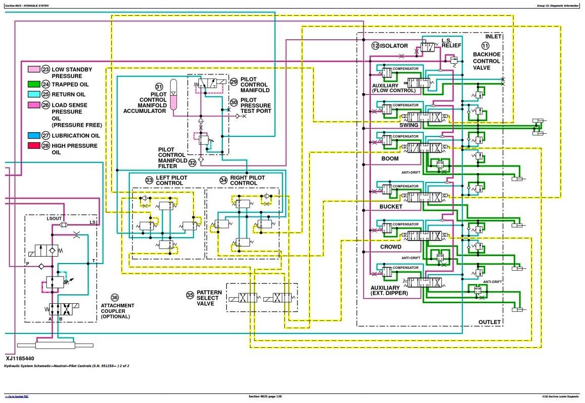
 The John Deere 410G dash wiring diagram typically includes elements, as switches, gauges, indicator lights, fuses, relays. components interconnected a series wires transmit electrical signals different parts the machine. wire color-coded numbered, allowing technicians easily trace .
![[DIAGRAM] John Deere 410g Wiring Diagram - MYDIAGRAMONLINE [DIAGRAM] John Deere 410g Wiring Diagram - MYDIAGRAMONLINE](https://777parts.net/repository/600x/johndeere/c2/l121351________un01jan94.jpg) Illustrated Factory Service Repair Technical Manual John Deere Backhoe Loader model 410G / Deere Technical Manuals. store; Shipping Delivery; Help; News; Brands; Contact Information; Меню . Diagnostic Manual electrical wiring diagrams sold separate. Language: English Format: PDF, 854 pages Covered models: 410G
Illustrated Factory Service Repair Technical Manual John Deere Backhoe Loader model 410G / Deere Technical Manuals. store; Shipping Delivery; Help; News; Brands; Contact Information; Меню . Diagnostic Manual electrical wiring diagrams sold separate. Language: English Format: PDF, 854 pages Covered models: 410G
![[DIAGRAM] John Deere 410g Wiring Diagram - MYDIAGRAMONLINE [DIAGRAM] John Deere 410g Wiring Diagram - MYDIAGRAMONLINE](/img/placeholder.svg)
![[DIAGRAM] John Deere 410g Wiring Diagram - MYDIAGRAMONLINE [DIAGRAM] John Deere 410g Wiring Diagram - MYDIAGRAMONLINE](https://www.epcatalogs.com/file/19f9b0e70ec59de4a7ea29fbcc337e9e264a193a/john-deere-410-backhoe-loader-tm1037-technical-manual-pdf.png) Complete Diagnosis, Operation Test Service Manual Electrical Wiring Diagrams John Deere 410G Backhoe, all shop information maintain, test, service professional mechanics. John Deere 410G Backhoe Loader workshop Operation Test repair manual includes: * Numbered table contents easy use that can find information need fast.
Complete Diagnosis, Operation Test Service Manual Electrical Wiring Diagrams John Deere 410G Backhoe, all shop information maintain, test, service professional mechanics. John Deere 410G Backhoe Loader workshop Operation Test repair manual includes: * Numbered table contents easy use that can find information need fast.
![[DIAGRAM] John Deere 410g Wiring Diagram - MYDIAGRAMONLINE [DIAGRAM] John Deere 410g Wiring Diagram - MYDIAGRAMONLINE](https://www.epcatalogs.com/file/10d8e252a86495b982fc10a0ac9e1f3c03717c2a/john-deere-410-backhoe-loader-tm1037-technical-manual-pdf.png) 410g backhoe loader. copyright 2000 (c) deere & company. data the property deere & company. use and/or reproduction specifically authorized deere & company prohibited.
410g backhoe loader. copyright 2000 (c) deere & company. data the property deere & company. use and/or reproduction specifically authorized deere & company prohibited.
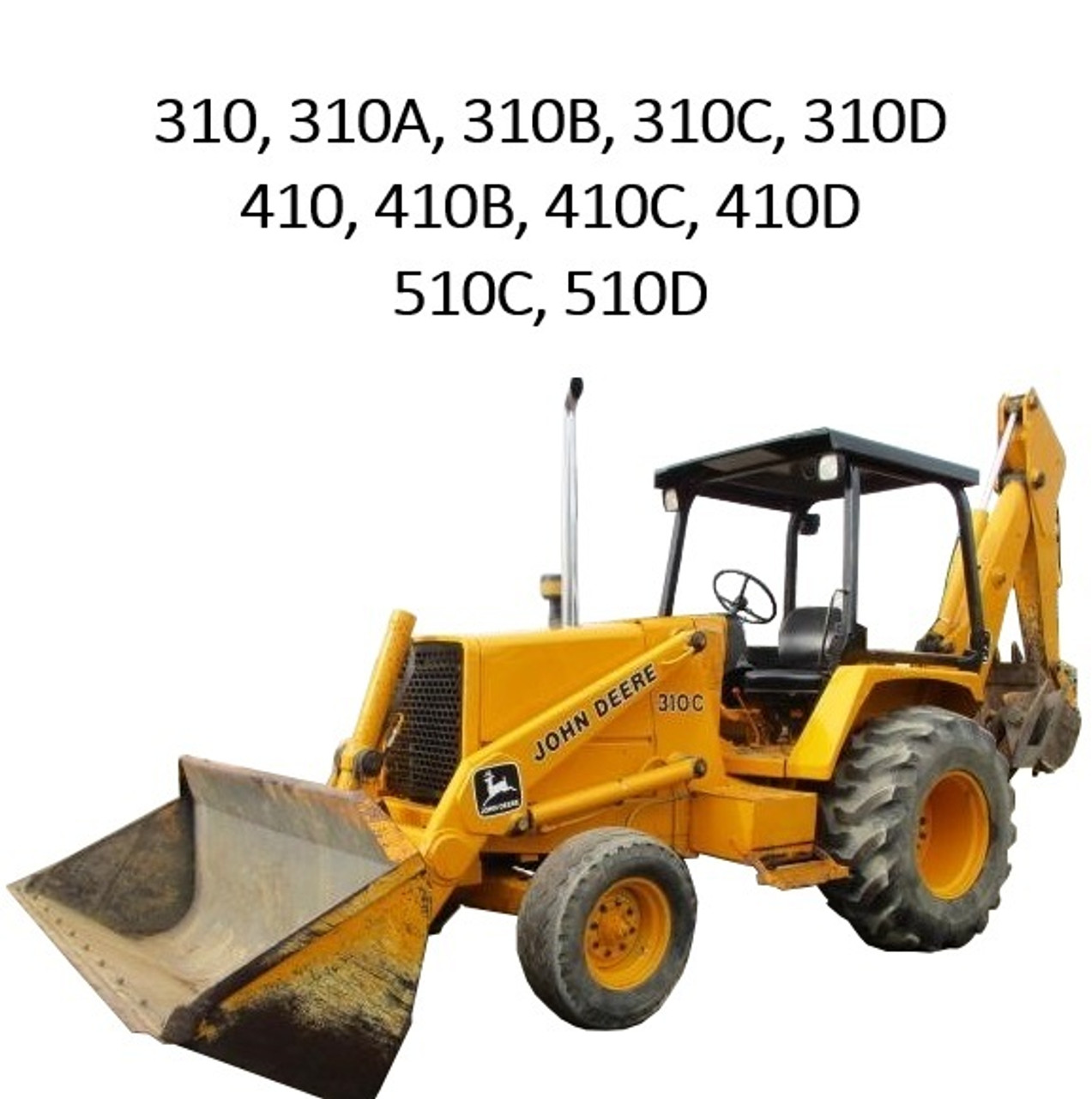
 Illustrated Factory Diagnostic, Operation Test Service Manual John Deere Backhoe Loader model 410G manual high quality images, diagrams, instructions help to operate, maintenance, diagnostic, repair truck. document printable, restrictions, searchable text, bookmarks, crosslinks easy navigation.
 Technical Manual John Deere 410 Backhoe Loader.This manual high quality images, diagrams, instructions help to operate, maintenance, Remove, troubleshooting, repair Loader. . Group 5 - Wiring Diagrams Group 10 - Charging System Group 15 - Starting Motor Group 20 - Ignition System Group 25 - Gauges Switches.
![[DIAGRAM] John Deere 410g Wiring Diagram - MYDIAGRAMONLINE [DIAGRAM] John Deere 410g Wiring Diagram - MYDIAGRAMONLINE](https://www.epcatalogs.com/file/dc3a9ff44ec4b9afefd6ab2717b09f9d395adda3/john-deere-2150-2255-tractors-tm4401-technical-manual-pdf.png) The wiring diagram the John Deere 410G backhoe illustrates various components their interconnections the electrical system. depicts battery, starter, alternator, solenoids, switches, relays, fuses, other important electrical elements. component labeled color-coded, indicating specific function .
The wiring diagram the John Deere 410G backhoe illustrates various components their interconnections the electrical system. depicts battery, starter, alternator, solenoids, switches, relays, fuses, other important electrical elements. component labeled color-coded, indicating specific function .
 Download John Deere 410G backhoe loader repair manual all series 2004-2022. Essential service maintenance guidance. . Wiring Harness Switches; Group 1675 - System Controls; Group 1676 - Instruments Indicators . manual/handbook useful mechanics, technicians, owners it detailed .
 John Deere 410B 410C 510B 510C Loaders Operation & Tests
![[DIAGRAM] John Deere 410g Wiring Diagram - MYDIAGRAMONLINE [DIAGRAM] John Deere 410g Wiring Diagram - MYDIAGRAMONLINE](https://www.epcatalogs.com/file/0c0189e173ad48af74c4b36d294685103588fc68/john-deere-410-backhoe-loader-tm1037-technical-manual-pdf.png) [DIAGRAM] John Deere 410g Wiring Diagram - MYDIAGRAMONLINE
[DIAGRAM] John Deere 410g Wiring Diagram - MYDIAGRAMONLINE
 TM1881 - John Deere 410G Backhoe Loader Diagnostic, Operation and Test
 John Deere 410g Wiring Diagram - Wiring Diagram
![[DIAGRAM] John Deere 410 Wiring Diagram - MYDIAGRAMONLINE [DIAGRAM] John Deere 410 Wiring Diagram - MYDIAGRAMONLINE](/img/placeholder.svg)
![[DIAGRAM] John Deere 410g Wiring Diagram - MYDIAGRAMONLINE [DIAGRAM] John Deere 410g Wiring Diagram - MYDIAGRAMONLINE](https://d12swbtw719y4s.cloudfront.net/images/eNAESAi5/6Wzj6k8EYBOvEGYXaSet/jT1KD64UjD.jpeg?w=1200) [DIAGRAM] John Deere 410g Wiring Diagram - MYDIAGRAMONLINE
[DIAGRAM] John Deere 410g Wiring Diagram - MYDIAGRAMONLINE
![[DIAGRAM] John Deere 410g Wiring Diagram - MYDIAGRAMONLINE [DIAGRAM] John Deere 410g Wiring Diagram - MYDIAGRAMONLINE](https://www.epcatalogs.com/file/base/7wCEvBLSdZwzQVEmrB3OWQivnhlQVAw+qqpCcivhkV6rvNeodUyoxJuIKs9DdUWqR4ru5FUDilXerWGRtGycYL6475Pas20HopTStAatpgN0/john-deere-8450-8650-8850-tractor-tm1256-technical-manual-pdf.jpg) [DIAGRAM] John Deere 410g Wiring Diagram - MYDIAGRAMONLINE
[DIAGRAM] John Deere 410g Wiring Diagram - MYDIAGRAMONLINE
 How to Decode a John Deere Wire Diagram: Step-by-Step Guide
 John Deere 410g Wiring Diagram - Wiring Diagram
 John Deere 410g Wiring Diagram - Wiring Diagram
