We've put a number networking diagrams help find you to install Humminbird fish finders, MEGA Live Imaging, Minn Kota trolling motors more, you take advantage the One-Boat Network ®. these wiring diagrams, can confident you'll start fish finder install process all the .
 Owner's Manuals. ICE HELIX Series Product Manual - English ; ICE HELIX Series Guide d'Utilisation - French ; ICE 35, 45, 55 Product Manual - English
 Attach black wire (-) ground, the red wire (+)12VDC power. NOTE: order minimize potential interference other marine electronics, separate power source (such a battery) be necessary. 3. Route power cable the Humminbird control head, insert connector the POWER-SPEED-TEMP port.
 If unit works correctly, tied the battery, recommend you at existing panel/buss, fuse and/or panel battery wiring. the wire gauge too small amperage power draw, can create issue. a 15-20' run cable, recommend 12-14 gauge, tinned copper stranded wire.
 Page 11 INSTALLING CABLES LCR equipped Humminbird's Angle-Lock power transducer connectors. power connector identified the letter P the of plug. Page 12 "Transducer". Note: adapter (AD-4) available allow of old waterproof (BNC) transducer the LCR, be that .
 8. the Humminbird Epoxy Kit equivalent, mix ample amount epoxy causing to bubble pour in area transducer to mounted. puddle be larger the bottom the transducer. 9. Coat bottom the transducer epoxy, put in center the puddle
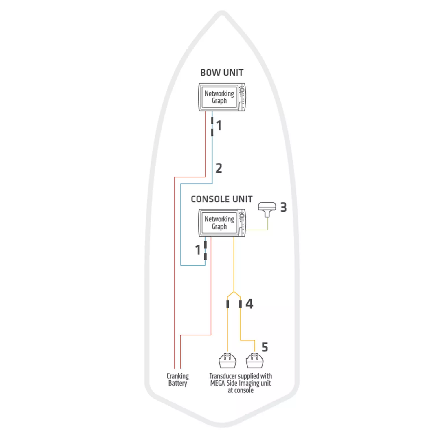
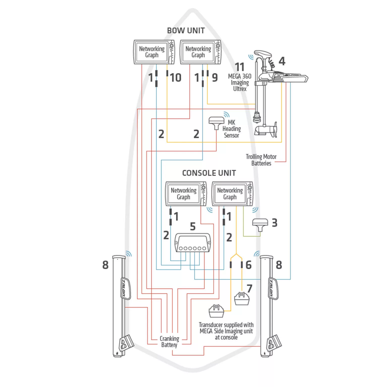
 Category: article. 22nd, 2020 Keith Worrall Modified 22nd, 2020 10:46 AM. Introducing new Installation Diagrams, designed help find you for boat rig correctly, you get the water quickly confidently. Browse the configurations download diagram help get started.
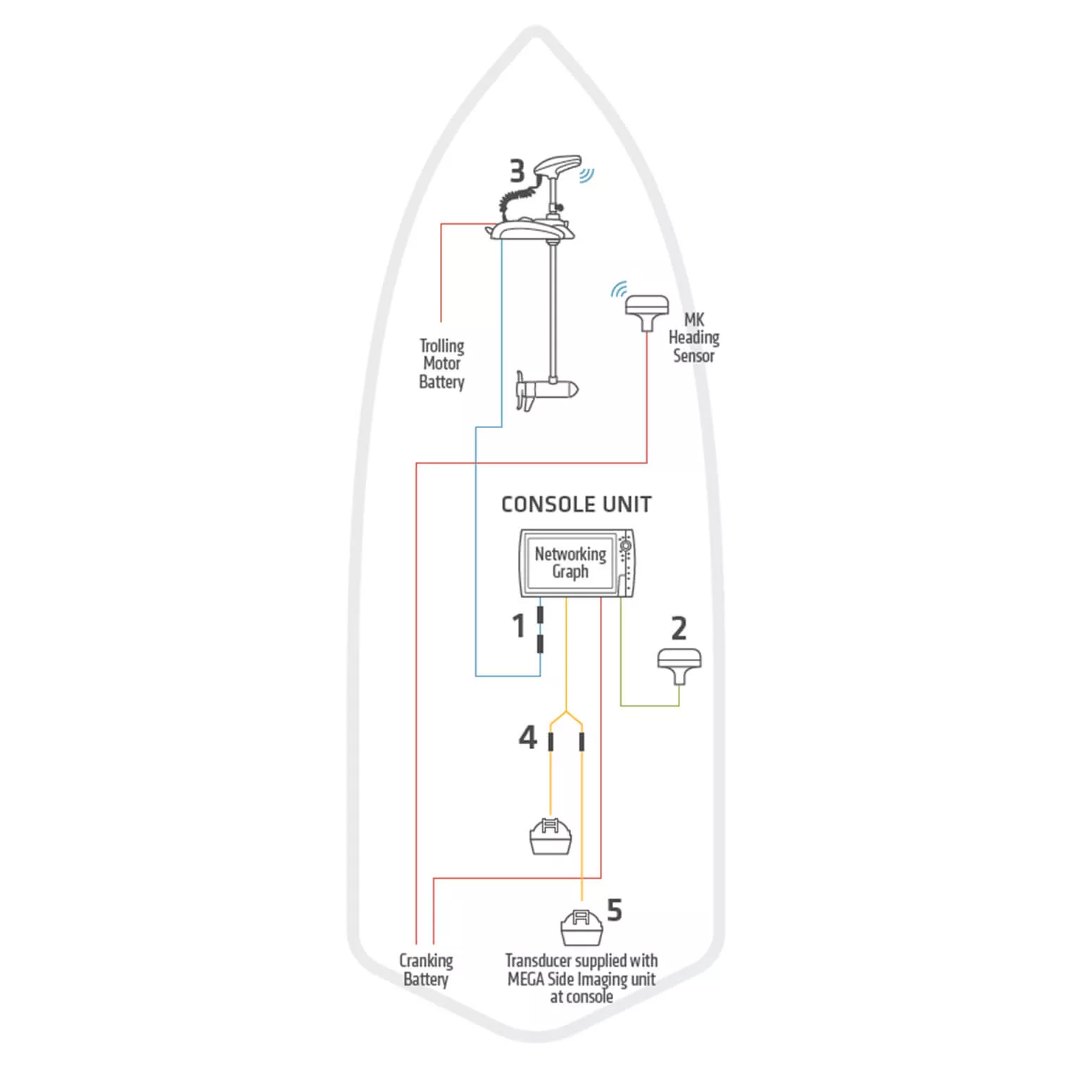
 INSTALLATION DIAGRAMS Console & Bow Mount Humminbird Units following schematic outlines necessary accessories/cables needed connect Humminbird units. Installation shown an . RS422 Data Ethernet DC Power Battery Battery 1 1 2 2 4 5 3 * accessories part numbers listed are valid of Oct. 2017. Installations .
 Humminbird Control Head/ Powered Accessory: Fuse Size Required (Slow Blow/MDL) Wire Gauge Required Power Cable Extension: Steady State Current Draw: APEX 19 CHARTPLOTTER: 7.5A: 1-6ft: 18 AWG: 6-12ft: 14 AWG: 12-24ft: 12 AWG: 4.4A: APEX 16 CHARTPLOTTER: 7.5A:
 Your Humminbird fishfinder work reliably water 2' (.6m) deeper. depth measured the transducer, necessarily the surface. Page 25 7. unit loses power high speeds. Humminbird fishfinders over-voltage protection turns unit when input voltage exceeds 20 VDC.
 Humminbird Lcd4id Power Plug Wiring Diagram Humminbird Netwo

 The Ultimate Guide to Humminbird Transducer Wiring Diagrams: Everything

 The Ultimate Guide to Humminbird Transducer Wiring Diagrams: Everything
 Humminbird Mega Live Wiring Diagram - Esquiloio
 The Ultimate Guide to Wiring Your Humminbird 360: A Step-by-Step
 Humminbird LCR 4 ID Fishfinder Head Unit Only With Cover Untested with
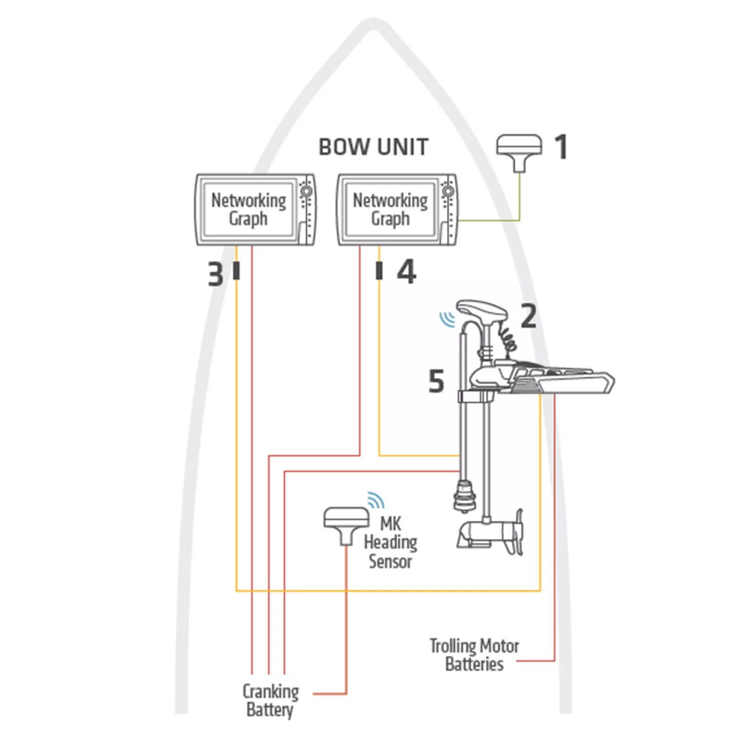 Humminbird Networking Diagrams - Humminbird
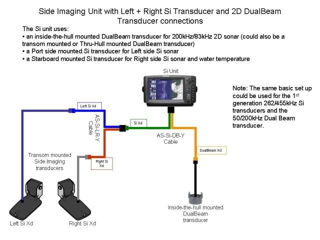 Humminbird Wiring Diagram
 18+ Humminbird Wiring Diagram - ShafaqatAimee
