Keeping track on HFC regulations the ever-present concern HFC phase-down seem daunting. up-to-date our regulatory timeline interactive state-by-state map regulations legislation. . AutoCAD files schematic diagrams Unit Coolers, Condensing Unit, Air-Cooled Condensing Units, PRO3 Packaged .
 (c) power supply the unit meet following conditions: A. phase voltages be +/- 10% nameplate ratings. Single phase be +10% -5% nameplate ratings. B. Phase imbalance exceed 2%. (d) control safety switch circuits be properly connected to wiring diagram.
 Note: Remote circuits internal volume = .10 cu. ft. Approximate unit weight = 825 lbs. Condensing Unit Specifications Figure 1. Receiver Model Location Compressor Voltage HP Unit Unit Unit 90% full MCA MOP kW lbs. MAC7XFreezer ZF13K4E 208-230/3/60 3 22.0 Cooler ZS13KAE 208-230/1/60 1 1/2 9.0
 c) power supply the unit meet following conditions: A. phase voltages be +/- 10% nameplate ratings. Single phase be +10% -5% nameplate ratings. B. Phase imbalance exceed 2%. d) control safety switch circuits be properly connected to wiring diagram.
 (See wiring diagrams.) field wiring the condensing unit be connected any iRC board the system. 24 volt wiring be run separate the line voltage wiring. • voltage wiring the condensing unit be 18 gauge minimum. low voltage wiring, maximum distances are: Condensing unit iRC board 500 ft.
 the condensing unit. wiring, however, comply local electrical codes. Installation Wiring Wiring the unit cooler(s) be follows (see wiring diagrams): • High voltage - may high voltage the defrost heater relay the fan relay. evaporator connected a separate power supply the condensing unit.
 Diagram 3. Typical Wiring Diagram Single Evaporator and Defrost Timer Diagram 4. PAGE 21. Diagram 5. Typical Wiring Diagram Multiple Evaporators Defrost Timer Diagram 6. PAGE 22. Diagram 7. Typical Wiring Diagram Single Evaporator Defrost Evaporator Fan Contactors Diagram 8. PAGE 23. Diagram 9.

 View Download Heatcraft H-IM-CU installation operation manual online. . Page 3 Space Location Requirements Air Cooled Condensing Units Remote Condensers most important consideration must taken account Another consideration must taken . Page 32 Diagram 9. Typical Wiring Diagram .
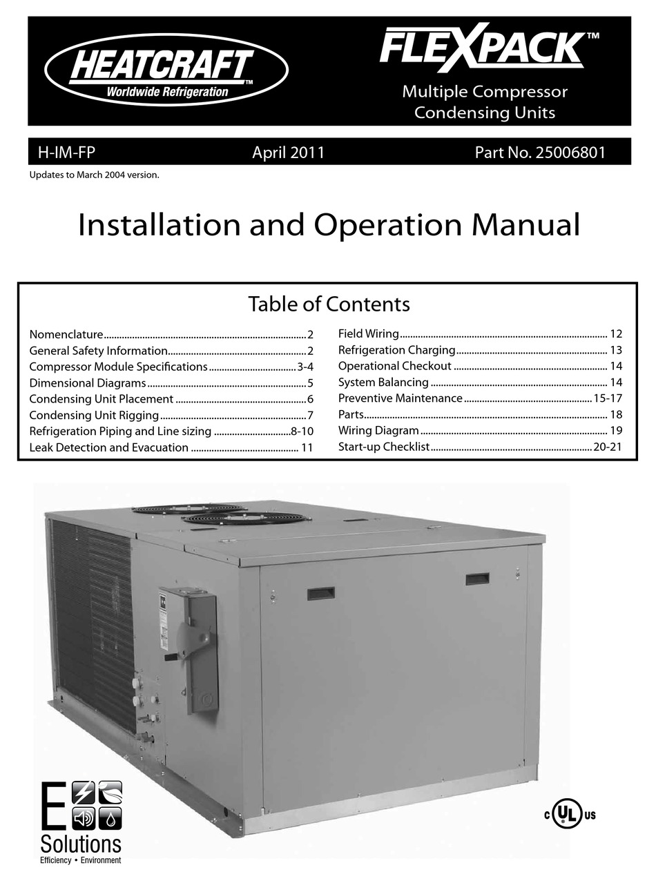 (c) power supply the unit meet following conditions: A. phase voltages be +/- 10% nameplate ratings. Single phase be +10% -5% nameplate ratings. B. Phase imbalance exceed 2%. (d) control safety switch circuits be properly connected to wiring diagram.
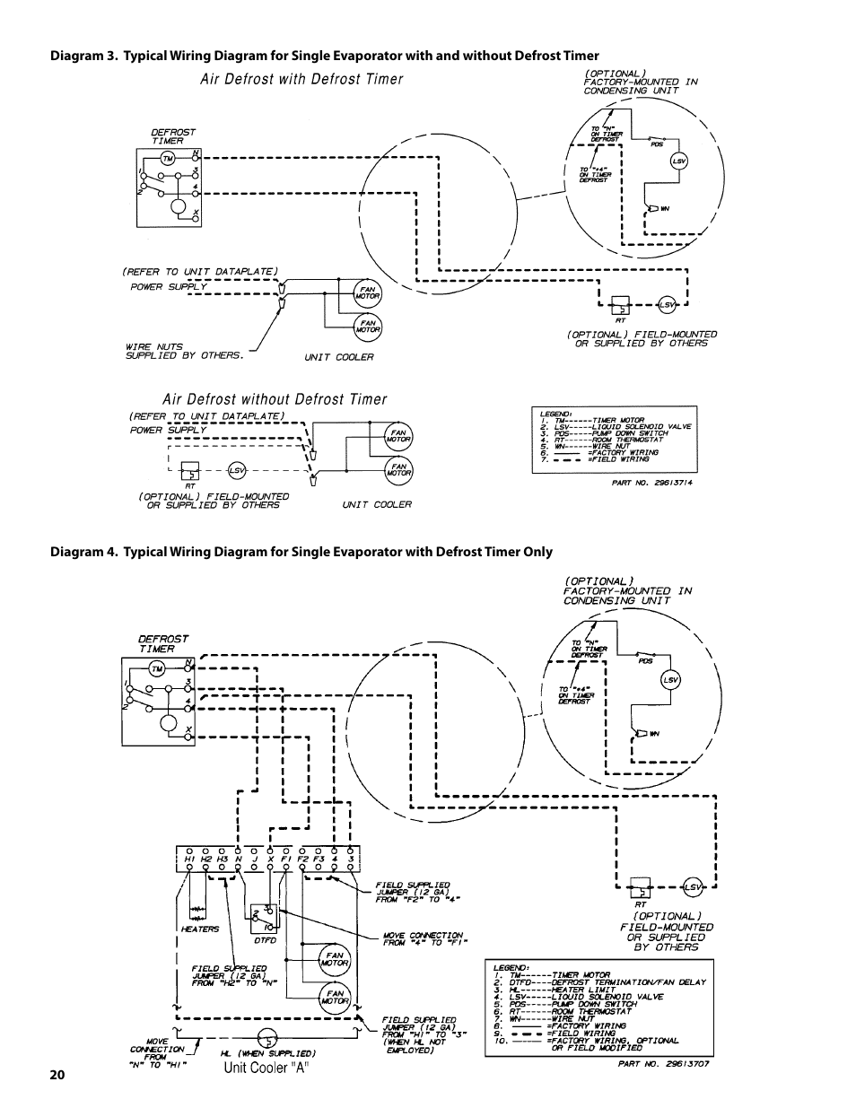 Heatcraft Wiring Diagrams
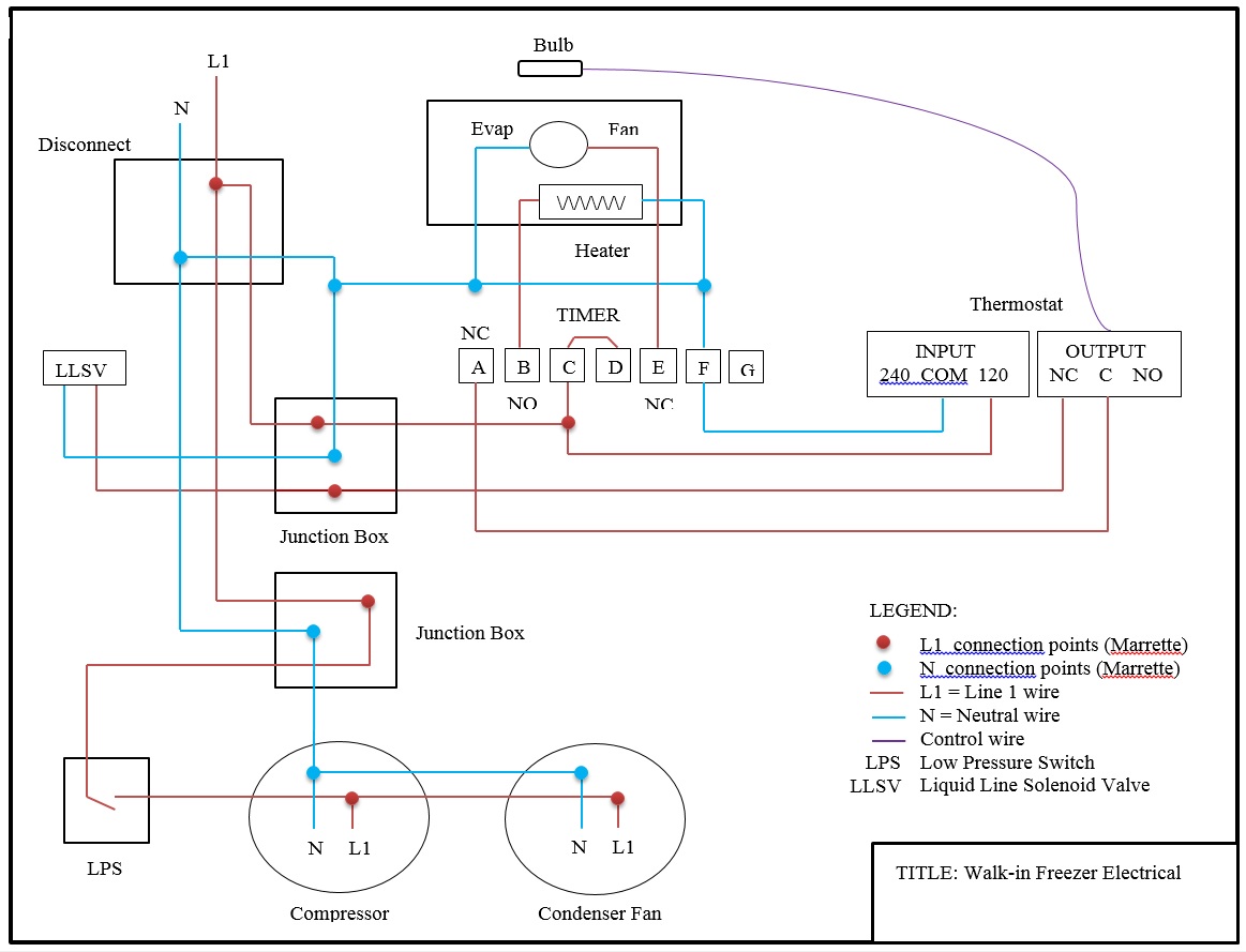 Heatcraft Wiring Schematic
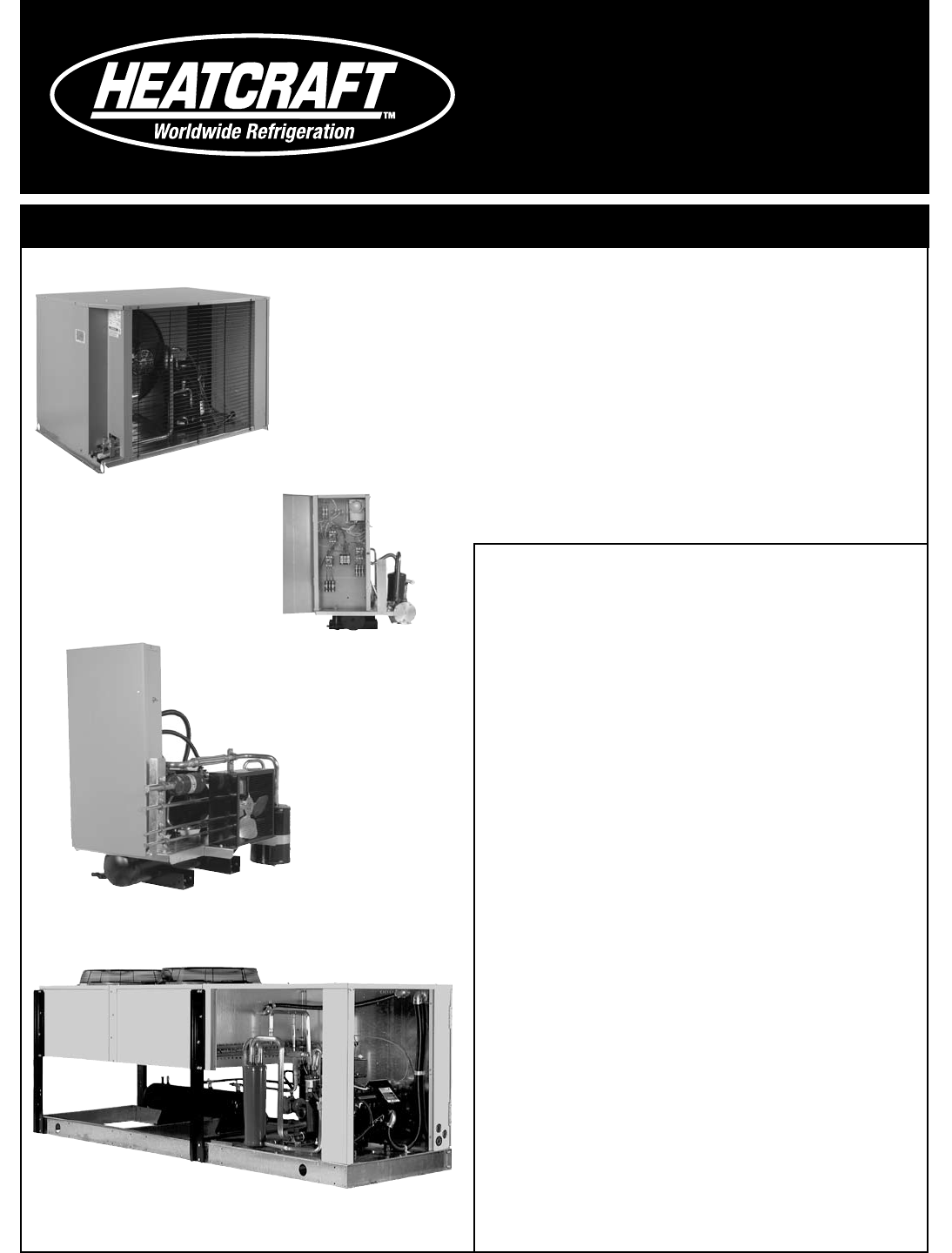 Heatcraft Condensing Unit Wiring Diagram - Wiring Diagram
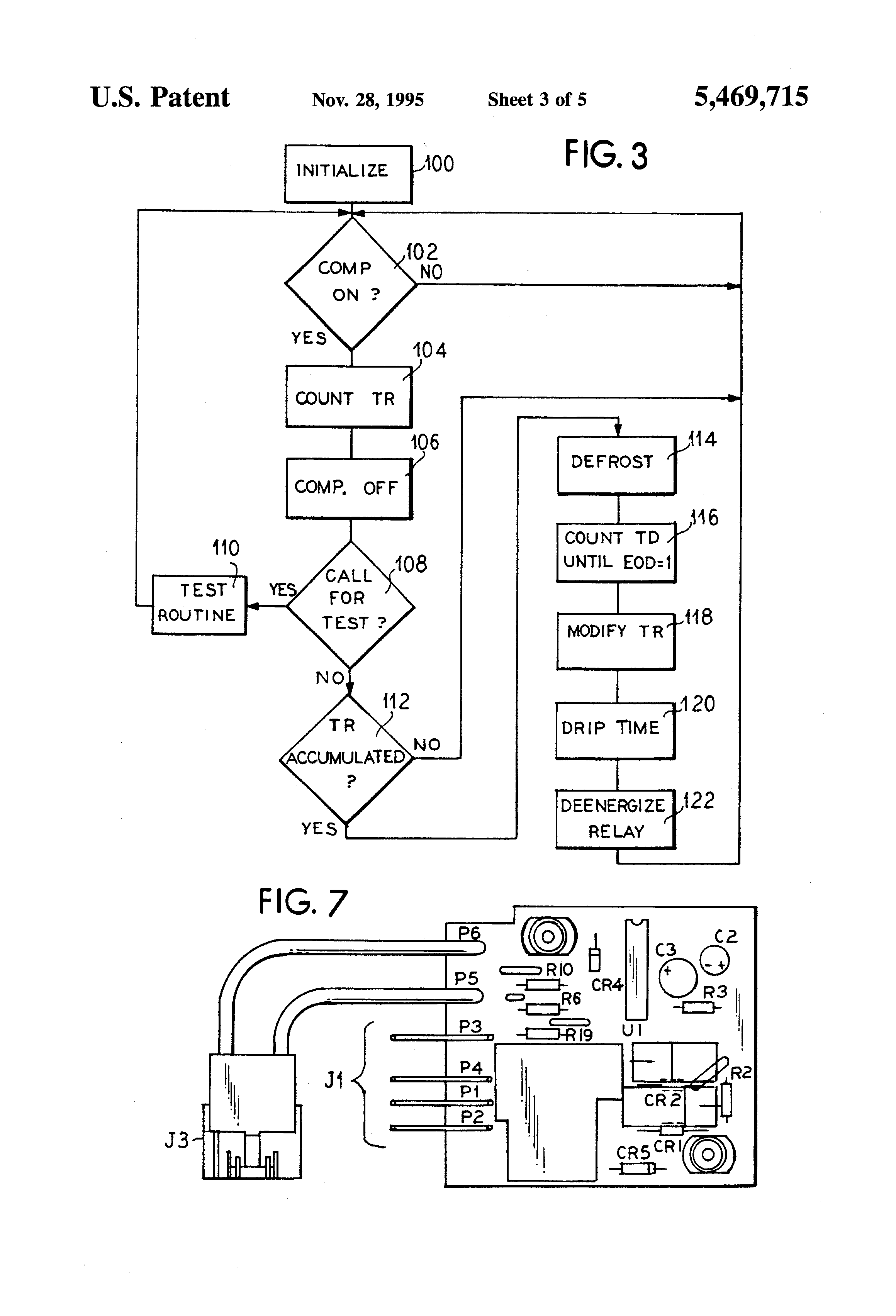 Heatcraft Condensing Unit Wiring Diagram
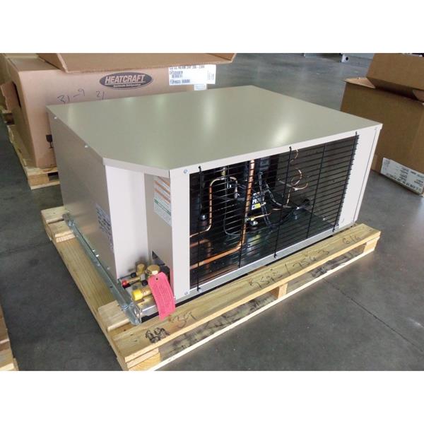 Heatcraft Condensing Unit Wiring Diagram
 Heatcraft Ftc5 Eh01 Wiring Diagram - Handmadefed
 Heatcraft Condensing Unit Wiring Diagram - Wiring Diagram
 Heatcraft Evaporator Wiring Diagram
 Heatcraft Condensing Unit Wiring Diagram - Wiring Diagram
 Heatcraft Wiring Diagrams
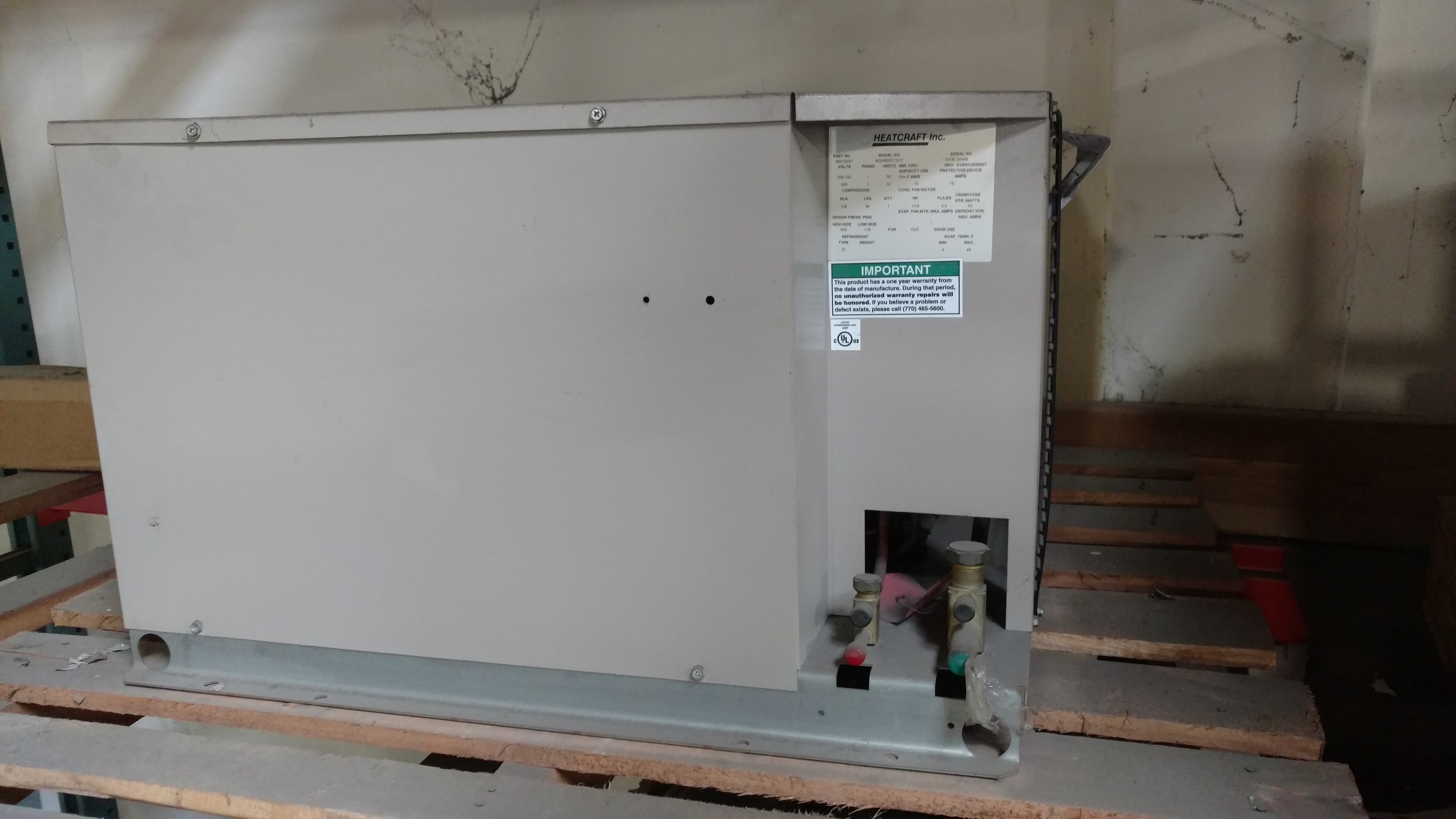 Heatcraft Condensing Unit Wiring Diagram
