The step wiring hall sensors any motor to figure how possible wiring combinations are. a 3 phase motor will 3 hall leads. hall sensors supply positive negative hall signal (meaning will 2 wires hall sensor), Galil servo amplifiers require positive lead .
 An Introduction Brushless Dc Motor Control. Bldc Motor Hall Sensor. Generate Own Commutation Table Tzoidal Control 3 Phase Bldc Motors Hall Sensors Technical Articles Ti E2e Support Forums. Long Lifetime 3000rpm Bldc Motor Sd Controller Brushless Dc Kit Holry. 500w 3 Phase Brushless Dc Motor Controller Driver .
 For my motor a 6 pin configuration. red wire obviously 5V pin, hall sensor 1, hall sensor 2, hall sensor 3 wires corresponded the color the 3 phase wires coming of motor. left with black white wire the ground temperature pin.
 I. Definition Hall Signals Hall-effect equivalent comcoder feedback signals be positive in phase the positive Bemf . • Summary Action Steps: the physical wiring a 3-phase motor drive Hall commutation feedback to change, order achieve specific motor direction a input .
 Contents. 1 HALL sensors Setup calibration 3-phase Motors (BLDC, PMSM , ACIM). 1.1 SOLO UNO wiring; 1.2 SOLO MINI wiring; 1.3 STEP 1 - Connect HALL outputs "Encoder/Hall Connector" SOLO; 1.4 STEP 2 - Find proper Motor wires connection SOLO; 2 Conclusion
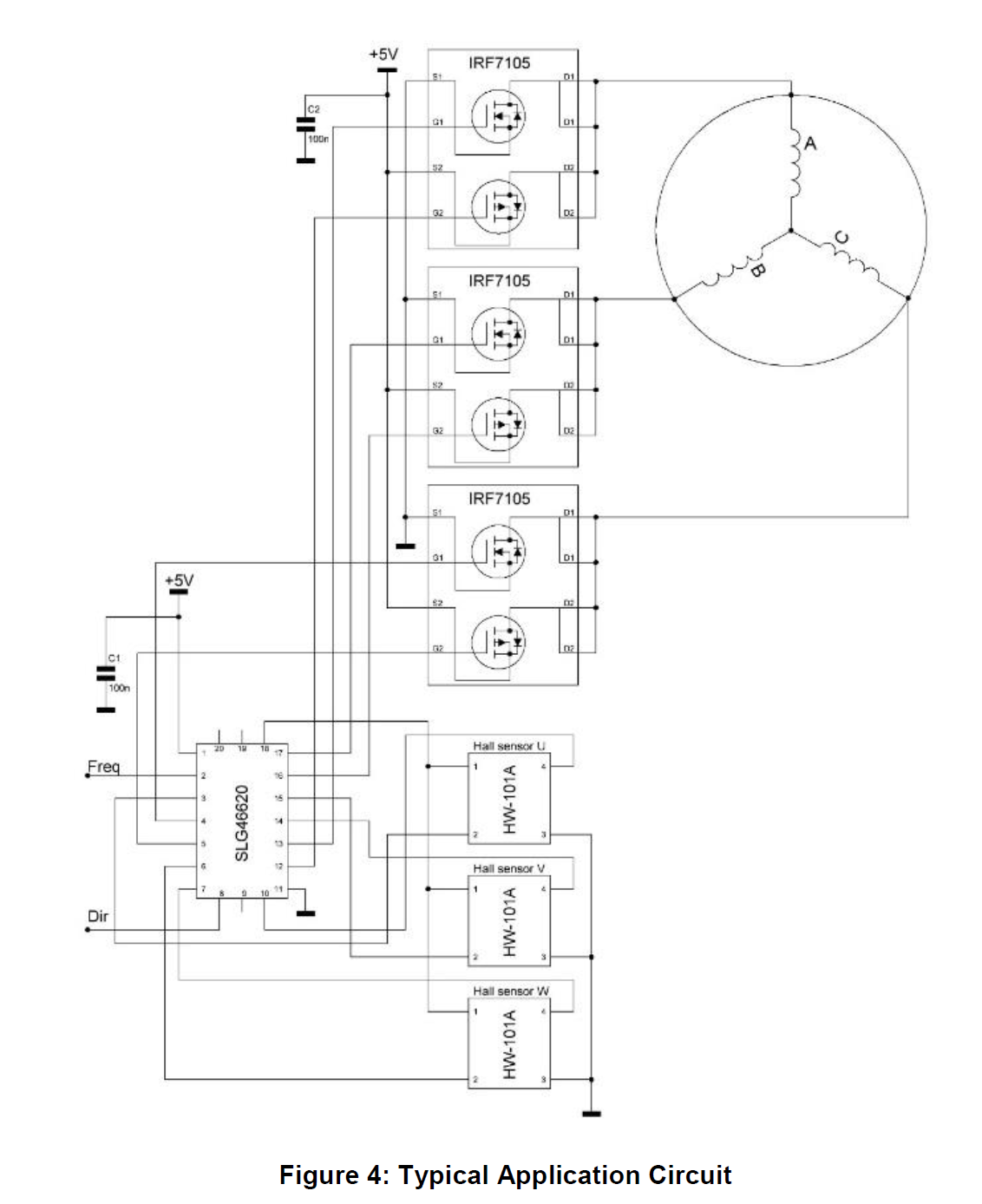
 BLDC motor operation scope shot Conclusion. article shows users control 3-phase brushless DC motor an SLG46620 GreenPAK CMIC Hall effect sensors. SLG46620 contains features can used this project. example, ADC the GreenPAK interpret input DC voltage generate PWM .
 Two major electrical systems to checked in typical BLDC hub motor has hall sensors. 1) motor's 3 phase windings. (high voltage components-thicker wires) 2) motor's 3 hall sensors, (low voltage components-thinner wires) present. not, will a "sensor less" capable controller skip tests.
 First, let's sort the motor's wiring. are wires, leads, running the motor. wires power motor are larger (16 AWG): Green, Blue, Yellow. wires power sensors are smaller: Red Black. three wires connect sensors the controller: Green, Blue, Yellow.
 A 3 phase motor a type motor operates three separate phases electrical power, its wiring diagram depicts connections these phases the motor itself. 3 phase wiring diagram motors typically includes information as voltage current ratings, type motor (e.g., induction motor .
 • three-phase stator currents measured. a motor balanced three-phase windings, two phase currents sufficient be measured. third current calculated the equation: ia + ib + ic = 0. • Clarke Transform: thr ee-phase currents converted a stationary two-axis system. conversion pro-
 3 Phase Motor Wiring Connections
 hall sensor controller « Brushless motors, 3Phase inverters, schematics
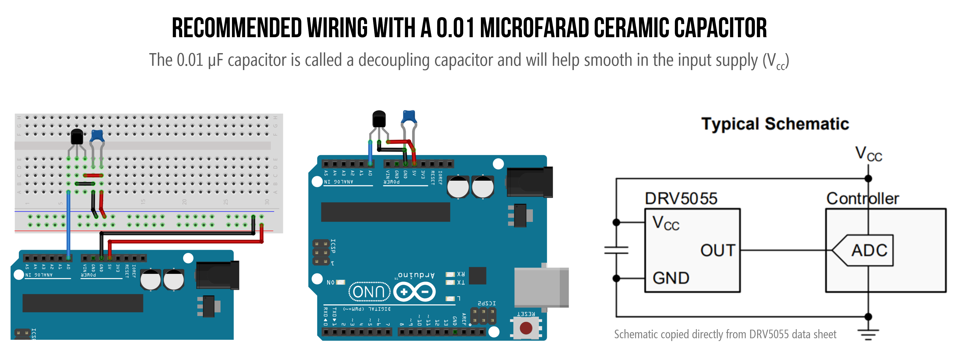 Hall Effect Sensors - Physical Computing
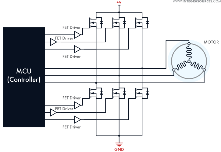 BLDC Motor Controller: Design Principles & Circuit Examples
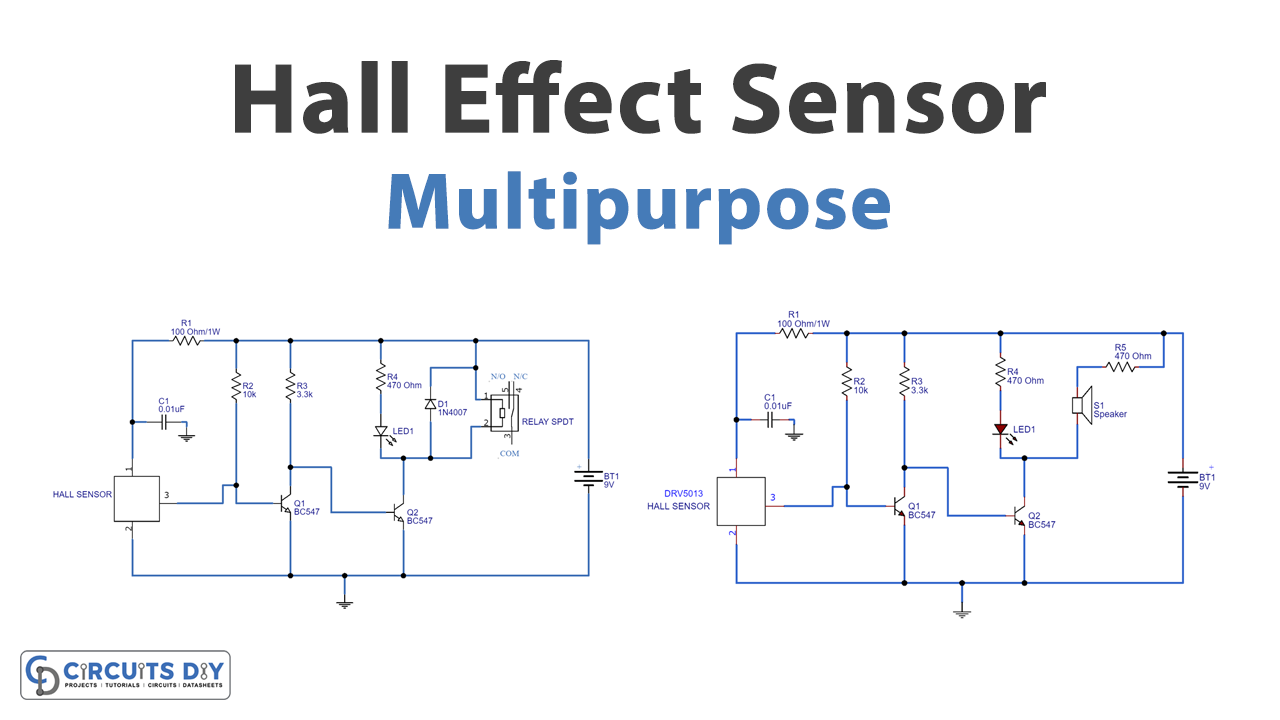 Multipurpose Hall Effect Sensor Circuit
 Three Phase Motor Wiring Connection
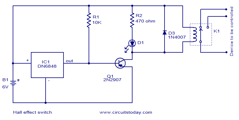 Hall Effect switch - Electronic Circuits and Diagrams-Electronic
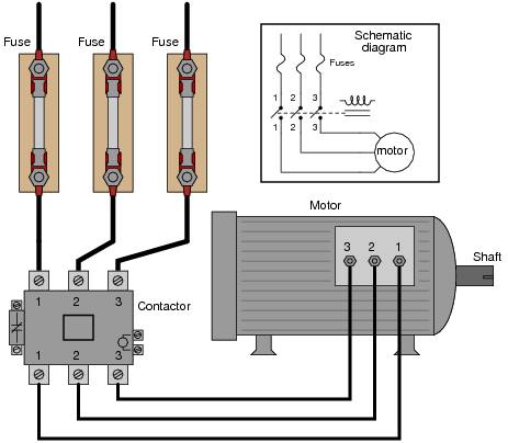 3 Phase Motors Wiring
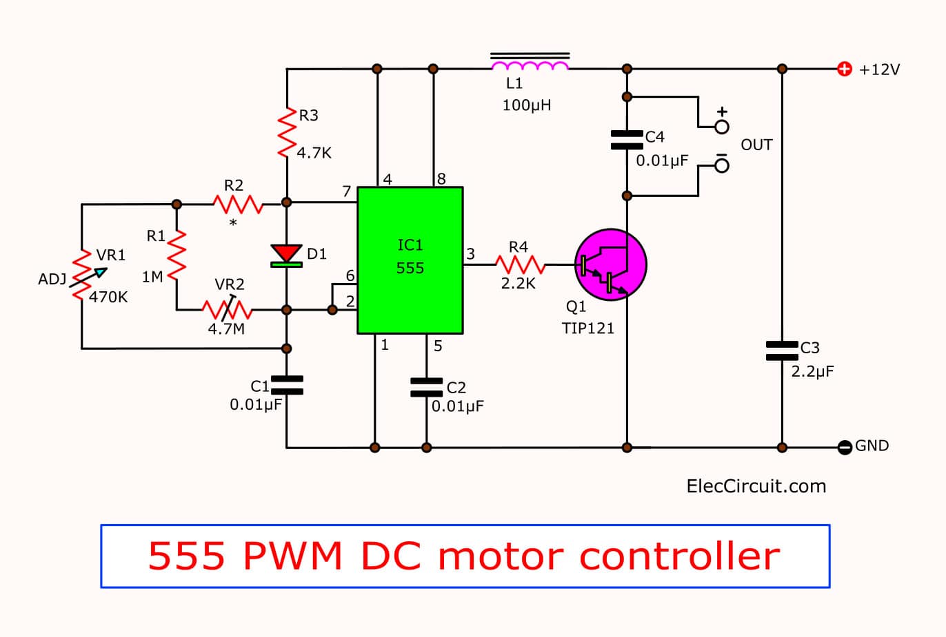
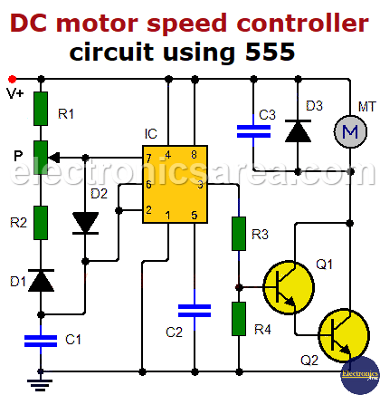 DC motor speed controller circuit using 555 - Electronics Area
 3-Phase Hall Sensor BLDC Driver Using Z32F128 MCU - EEWeb
 3 Phase Bldc Motor Working Principle | Webmotororg

