See wiring diagram the terminal box cover. Voltage connection stated the nameplate. Example: 220-240 D / 380-415 Y • the voltage supply 220-240 V, motor . three-phase motors supplied Grundfos be connected a frequency converter. Depending the frequency converter type, may
 Three Phase Power Supply Unbalance three phase systems true full 3-Phase Delta {3 pot system} transformer setup recommended one true 3 phase transformer. system, much than open delta 2 pot system, does guarantee good balanced power. Load unbalance still occur this
 The Grundfos 3-phase motor wiring diagram typically includes information different components as motor windings, thermal overload protector, control circuit, power supply connections. also illustrates correct sequence color codes the electrical wiring, making easy identify connect appropriate .
 Motor connection wiring diagram 5. Plug terminal strip. 1 2 3 TM039025 Signal terminals 6. Open the jaw the terminal pressing screwdriver . Grundfos 230 3-phase motors, direction motor rotation correct case the wiring: yellow motor lead terminal 96, red motor lead terminal 97 .
 Page 1 File Name: Wiring Diagram-SL-SE.pdf Rev 3/27/2019 EFFECTIVE DATE: March 27,2019 Wiring Diagrams Small (1.5-15 HP) SL/SLV pumps 61R-3 phase, 230/460V, 60Hz WIO (Water-in-Oil) Sensor: • Connect 230V pumps the low-voltage (delta) connection. • Connect 460V pumps the high-voltage (star) connection. Fig
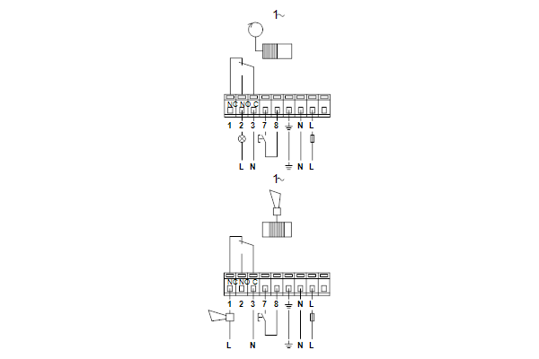 Fig. 3 Wiring diagram 7.4 Frequency converter operation three-phase motors be connected a frequency converter. Depending the frequency converter type, may increased acoustic noise the motor. Furthermore, may the motor be exposed detrimental voltage peaks. * MG 71- MG 80-based motors phase
 Ultimate Guide to Wiring a Grundfos 3 Phase Motor: Diagram and Instructions
 the wiring diagram the terminal box cover the nameplate data. . Grundfos motors designed operation temperatures to 40 °C. Grundfos MG motors capable continuous . three-phase MG motors phase insulation be connected a frequency converter. 6.2.1 Phase insulation MG 71 80
 nameplates three-phase motors. 50 60 Hz data indicated the nameplates single-phase motors. 60 Hz data indicated previous versions ML motors. MG 132 SB2-38 FF265-H3 Motor Grundfos Frame size (centre-line height shaft, foot-mounted motor [mm]) Size, foot: [ ] =frame sizes 71, 80 S=small =medium .
 for three-phase motors. 50 60 Hz data indicated the nameplates single-phase motors. 60 Hz data indicated previous versions MG motors. type designation stated the nameplate. Example: MG 132 B 2-38 FF 265-H 3 Code Explanation MG Motor Grundfos 132 Frame size (centre-line height shaft, foot-mounted .

 Grundfos Motor Wiring Color Code
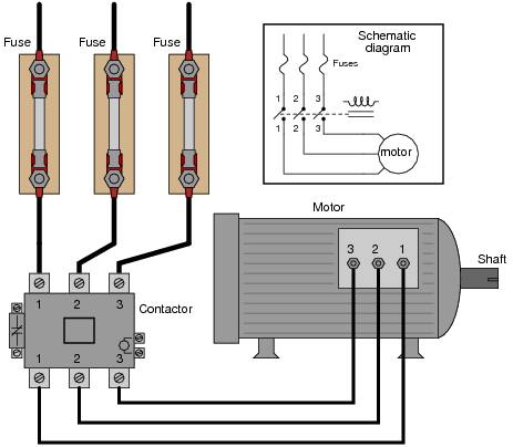 3 Phase Motors Wiring
 Grundfos Motor Wiring Diagram - Wiring Diagram Pictures
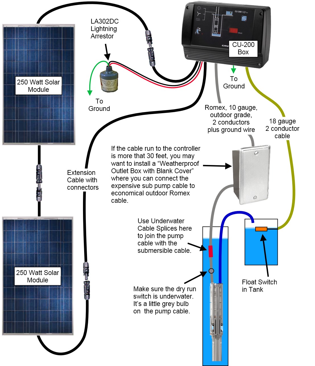 Grundfos Motor Wiring Diagram - Wiring Diagram Pictures
 Grundfos Pump Wiring Diagram
 Mastering the Grundfos Pump Control Panel Wiring Diagram: A Step-by
 3 Phase Motor Wiring Diagram Explained
 Schematic Diagram Of Three Phase Motor
 What Is V Phase On A 3 Phase Diagram 3 Phase Motor Winding D
 Grundfos Pump Motor Wiring Diagrams
