Phase Loss Phase Sequence Phase Asymmetry Yes 10% (of ) LED Indication Separate indications Power ON, UV OV; ON: Phase Reverse; BLINK: Phase Asymmetry Utilization Category AC - 15 DC - 13 Rated Voltage (Ue): 120/240 V, Rated Current (Ie): 3.0/1.5 Rated Voltage (Ue): 24/125/250 V, Rated Current (Ie): 2.0/0.22/0.1 Output Contact .
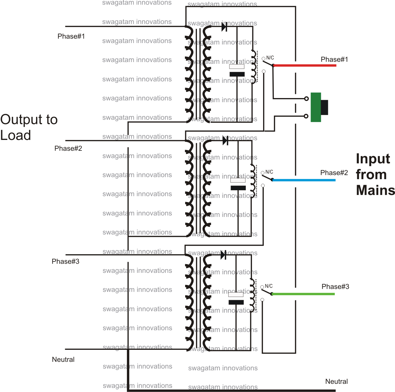
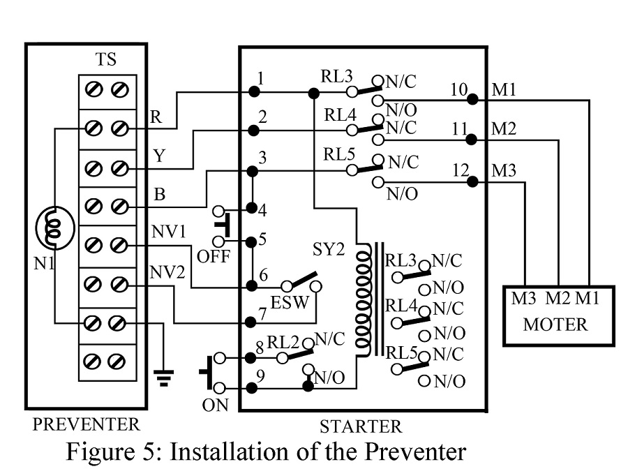
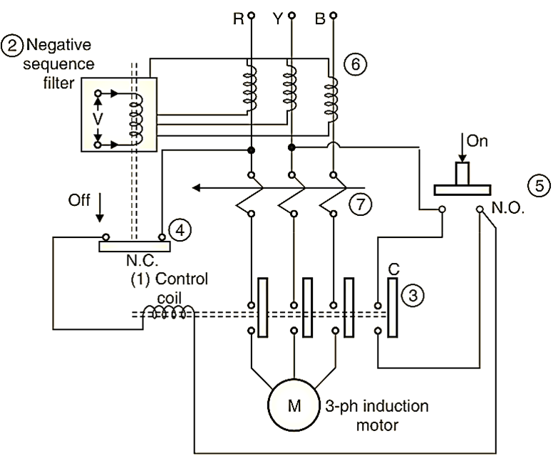 Without GIC single phase preventer wiring diagram, can difficult even impossible figure how hook your system correctly. Understanding wiring diagram critical it to installing single phase preventer. diagrams often comprehensive, require considerable amount knowledge .
 CONNECTION DIAGRAM L1 L3L2 SM 175 15 16 18 Y B . Single Phase Voltage Relay MF51B0 400 VAC, Phase Voltage Relay . Cat. No. Parameters MD21DF MG21DH MG21DF MGD1DR 208 - 480 VAC, (3 Phase 3 Wire) 400 VAC, (3 Phase 3 Wire) Supply Variation Supply Voltage ( )-12% + 10%(of ) Power Consumption (Max.) 3 VA Frequency 50/60 Hz .
 *All LEDs off incase Single Phase Loss, 2 Phase Loss & 3 Phase Loss conditions. 2 C/O (Minimum load 5mA recommended) . Blinking N.A. SUPPLY MONITORING DEVICE, SERIES: SM500, 3-PHASE 4-WIRE 1-PHASE MGH3BF AC 240 VAC MGH3BY ~500 ms. SUPPLY MONITORING DEVICE SERIES SM500 1-Phase 3-Phase 4-Wire l MG73B9, MG73BH, MG73BF .
 Note 1:- ON: Relay ON, OFF: Phase Loss, Blinking: Asymmetry (200 ms, On/Off), Flashing: Phase Sequence (1 s, On/Off) Cat. No. MC21B5 Parameters Frequency Power Consumption (Max.) 415 VAC 50/60 Hz 15 VA Supply Voltage ( ) Trip Settings Phase Loss Phase Sequence Phase Asymmetry Yes Hysteresis Time Delay Delay Trip Time (OFF Delay) < 550 ms .

 • Phase loss (failure) detection • Neutral loss detection • Phase reverse detection . CONNECTION DIAGRAM TERMINAL TORQUE & CAPACITY L1 L2 L3 SM 500 15 16 18 25 26 28 P P L1 L3L2 SM 301, SM 501 15 16 18 25 26 28 . SINGLE PHASE PHASE MOUNTING DIMENSION (mm)
 3 Phase 4 Wire, UV/OV & single phasing Protection adjustable 0 15 Off delay time, 2 C/O 3 Phase 4 Wire, UV/OV & single phasing Protection adjustable delay , 2 C/O0 15 time Supply Voltage (Un): Frequency Power Consumption 3 Phase 4 Wire, 240 VAC 1 Phase, 240 VAC 48 - 63 Hz 5VA 55% - 95% Un 105% - 125% Un 10% Yes
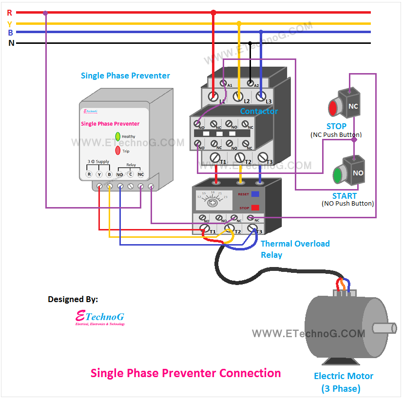
 The circuit made per diagram shown the circuit tested creating single phase fault swiching any phase a time. . single phase preventer prevent make circuit. Apparatus Used: . Maker's 1. Single Phase Preventor 3 phase, 1NO, 1NC, 415 V, 50 Hz, DIN mount: 1 GiC 2. Contactor Block 3 phase .
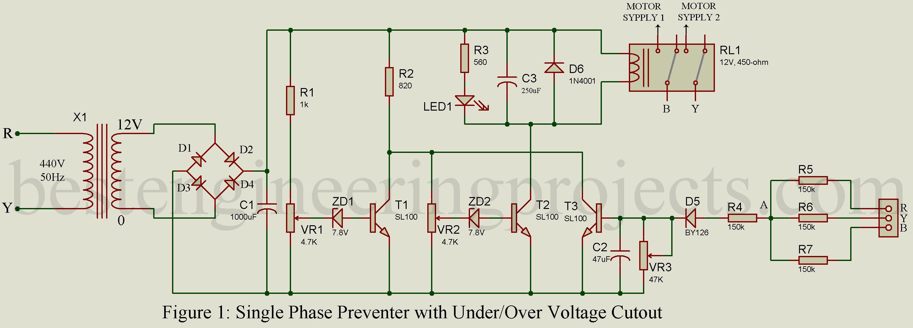 A wiring diagram single phase preventer used protect circuit breakers overloading, can insulation breakdown other problems. preventer ensures power supply voltages remain the desired range. . Single Phase Preventer Power Contactor Gic Distributor Channel Partner Delhi. Ellico Controls .
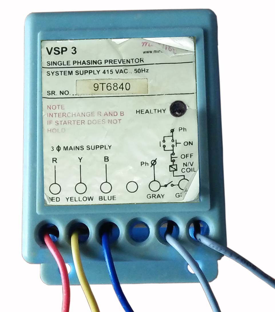 Automatic Single Phase Preventer Circuit Diagram
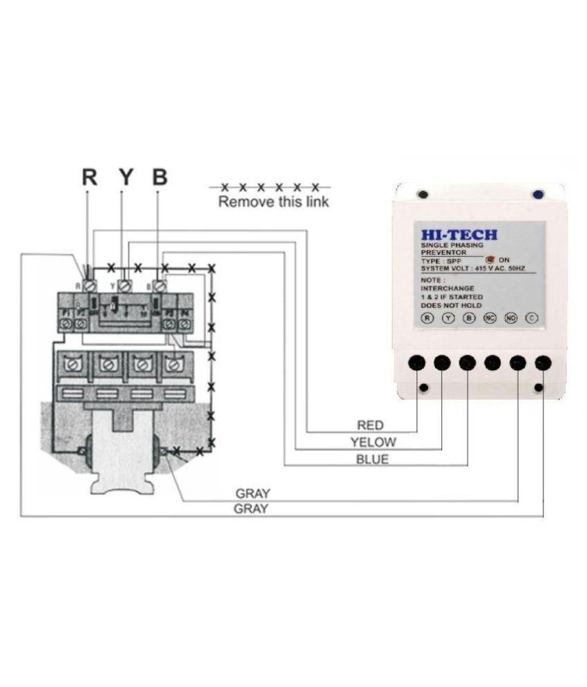 Wiring Diagram Single Phase Preventer - Wiring Diagram
 Single Phase Preventer Wiring Connection Diagram | Phase Failure Relay
 Single Phase Preventer Wiring Diagram
 Working and connection diagram of Single Phasing Preventer - ETechnoG
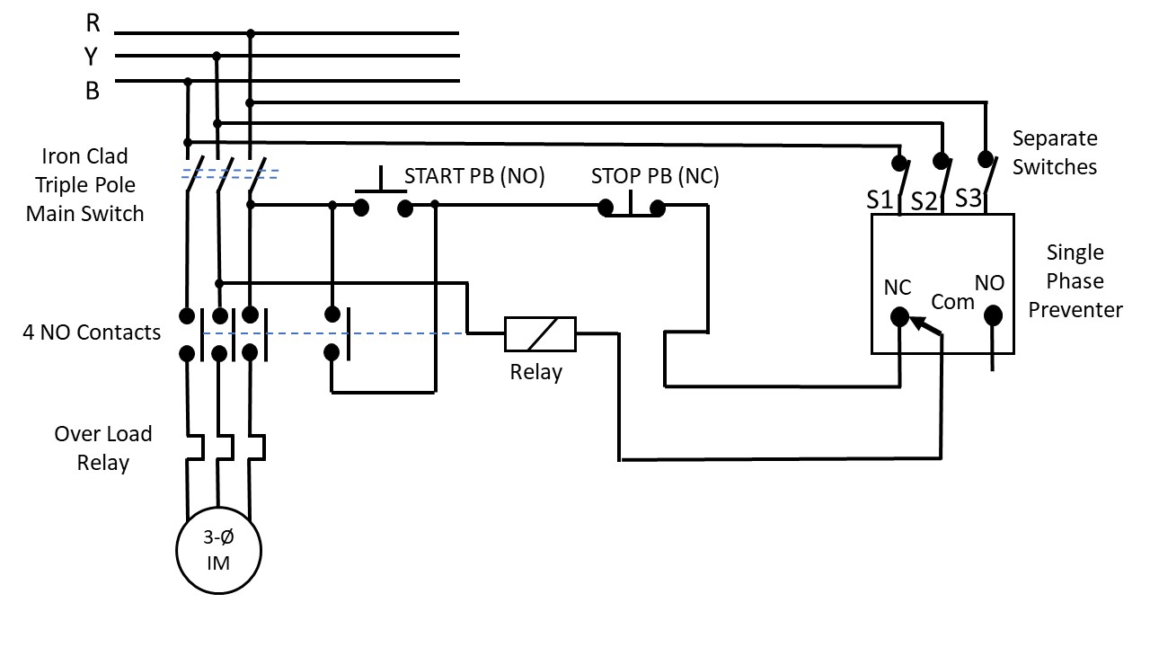 Practical Operation of Single Phasing Preventer Experiment


 Single Phase Preventer Circuit Diagram Pdf - Circuit Diagram
 Single phase preventer connection | Engineers CommonRoom ।Electrical
 Single Phase Preventer Circuit Diagram
