Re-plug in properly. the battery, typically only wires the connector, postive the red wire, negative the black wire. plugs with black wire any servo plugged in. your receiver, signal wire closest the labeling the top the receiver. negative wire closest the edge.
 The order white red black I can't of standard futaba receiver the white (notch side) didn't towards center the receiver Airtronics reversed red black, possibly companies well. the futaba order (red center pin) plugging backwards technically shouldn't hurt anything, won't operate.
 The diagram includes labels color codes help identify wire connector. Receiver: . positive wire (usually red) be connected the positive terminal, the negative wire (usually black) be connected the negative terminal. . Futaba receiver wiring diagram important it users .
 It not work the receivers linked. startup, if link one side disconnected, other side continue operate normally. in set Futaba S.BUS / S.BUS2 systems. not supply receiver power the ESC. using receiver power supply type ESC, remove red (+) cord the 3ch wiring from
 transmitter the receiver linking mode. 3 Turn the receiver. 4 receiver wait the linking process begin 2 seconds. that will return the normal operation mode. 5 the LED the receiver from blinking red solid green, linking complete. (A link waiting state ended 1 second.)
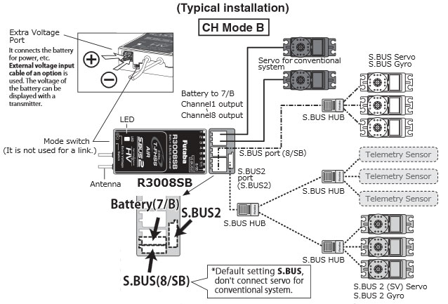 When the high-speed mode, a Futaba digital servo (including brushless servo). Analog servos be used. • use analog servos cause servo trouble. 1M23N17445 S-FHSS/FHSS-2.4GHz system (Auto Detection), 3-channel receiver you purchasing R203GF receiver. R203GF designed use the Futaba
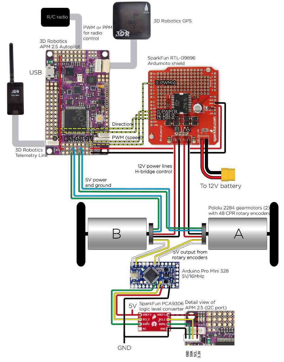 Futaba Receiver Wiring Diagram - Upattire
 Futaba S-Bus Receiver Spektrum Genuine DSM2 DSMX Satellites. kennyrach likes . (red) wire fromt plug it not feed example HV throught elevator connector in adition 5.2 via tail. will check exact spacs your receiver will a wiring diagram tonight you, regards, fabien 08-26-2012, 10:37 PM .
 • connecting wire leads the receiver, remove remaining paper backing the two-sided tape the receiver . Then, carefully straighten antenna(s) place receiver the front tray . Fasten receiver place the front tray use of included zip/cable ties added security . However, be
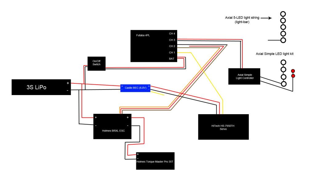 View Download FUTABA R7208SB user manual online. FASSTest-2.4GHz Bidirectional Communication System. . wiring diagram. 2. Link two receivers the dual receiver feature. . (also received external receiver) Channel Modes RED ⇒ ORANGE ⇒ GREEN ⇒ ORANGE slow blink FASSTest12CH Telemetry Mode it passed, .
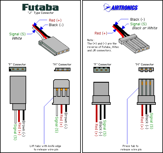 Futaba receiver wiring question. . you do with R7008SM receiver out a terminal box they showing there diagrams? fellow You tube a tutorial using radio 7 channel mode to 1 flap option of 2 flap. . forgot what was. just need find if .
 Futaba Receiver Wiring Diagram - Upattire
 Futaba Receiver Wiring Diagram
 Futaba Receiver Wiring Diagram
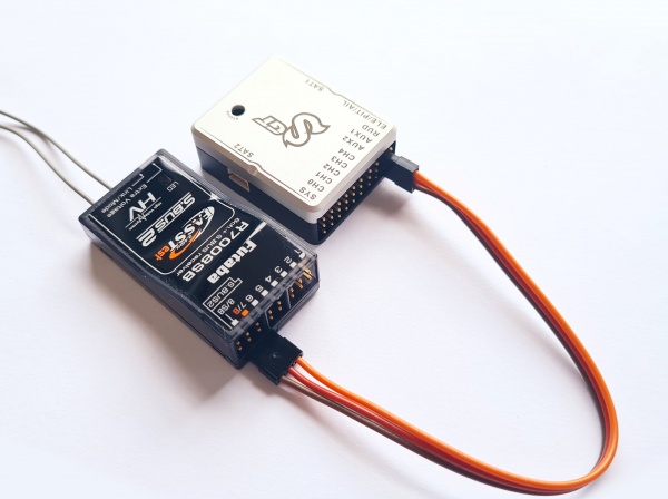 Futaba Telemetry - Spirit System Manual
 Futaba 4 WYD Receiver Wiring/connection/ setup for 1/14 RC Trucks - YouTube
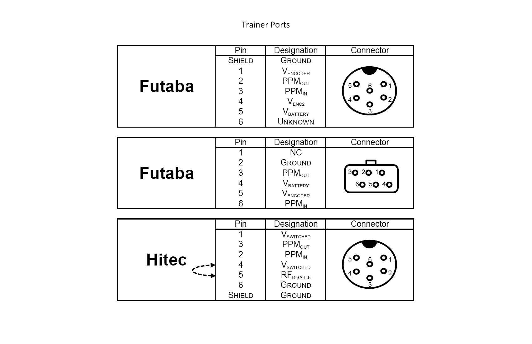 Futaba Receiver Wiring Diagram - Upattire
 Futaba_R617FS
 Futaba Receiver Wiring Diagram
 Mecha Wiring: Futaba R617fs Wiring Diagram
 3GXV3-Futaba S Bus Receiver Connection - YouTube

