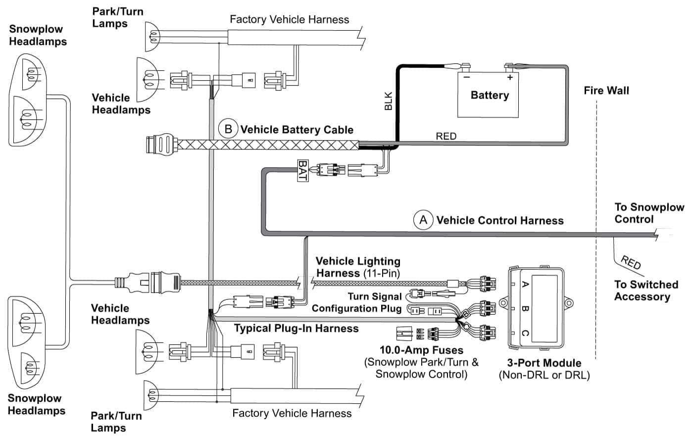
4-PORT ISOLATION MODULE LIGHT SYSTEM w/3-PLUG SYSTEM HARNESSES Installation Instructions . TYPICAL SYSTEM DIAGRAM 43 21 Isolation Module Park/Turn Lamps Factory Vehicle Harness . (7-Pin - V-Plow) Snowplo Control Switched Accessory BLK BLK/ORN Motor Relay RED. Lit. No. 28561, Rev. 04 4 24, 2007 8436, 8437-1, 8438, 8439, 8442 .
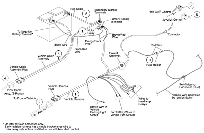
 3. Find location the hood the motor relay it be protected road splash will within 18" the vehicle battery. NOTE: Motor relay terminals be or horizontal. 4. Drill 9/32" mounting holes the motor relay mounting plate a template. Mount motor relay the holes 1/4" 3/4" cap screws,
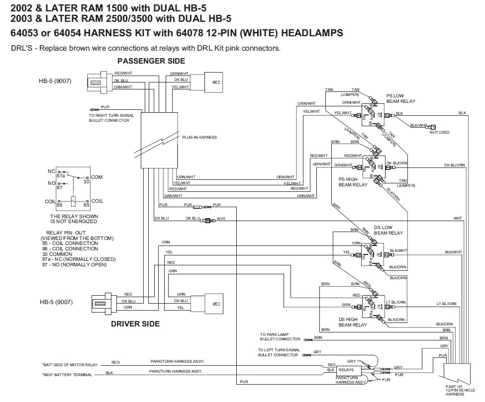
 4 3 5 2 1 PLOW ASSEMBLY #6 BLK/RED #6 BLK/RED YEL (LOW) VEHICLE HEADLAMPS GRY BRN BRN PUR BLK/ORN (GROUND) . Fisher Engineering. No. 22372 2 1998 Contents . verify correct light kit/plug-in harness a vehicle, refer the Kit Selection Guide.
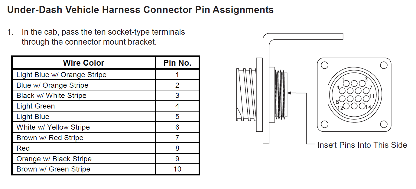
 This also good adapting Fisher joystick another pump set up. will help quickly diagnosing wiring issues well. T.J. Attachments. Fisher Joystick schematic.doc. 38.5 KB Views: . me color wires the harness (from iso box) to colors the joystick harness (deleting plug) .
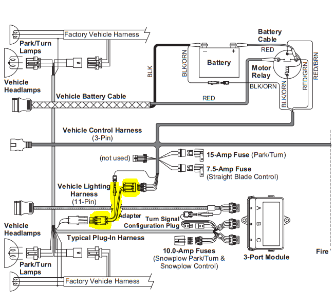
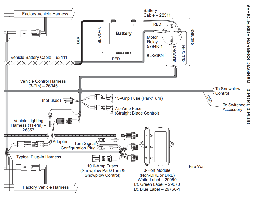
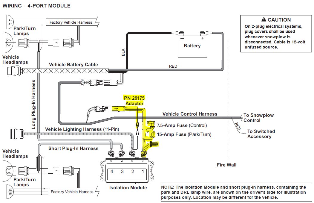
 Here will find answers these questions: 1. is difference 3 4 port modules? 2. the 3 4 port module better? 3. module my truck need? 4-Port Module 3-Port 3-Plug Straight Blade Kit Link you didn't know, Western Fisher the wiring. now the Fleet Flex.

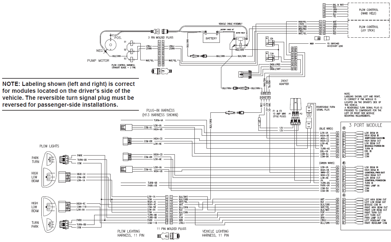 The Fisher Plow 4 Port 3 Plug wiring diagram divided two main sections. first section labeled "Main Power Supply". includes power cable, battery terminal, the main fuse block. this section, you'll able identify wire figure which used what.

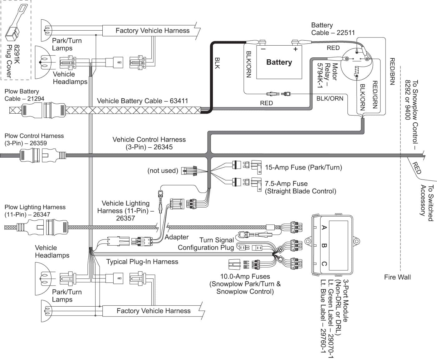 If plow a 2-plug system, also this 28053 convert over 3-plug. Note: Fisher uses Multiplexing system. your control 4 pins of 6, 2 plugs the grille of 3, is the correct wiring your plow.
 Grille Plug Plug Cover Vehicle Grille Plate Harness 1. Turn the vehicle ignition. 2. Disconnect negative (-) positive (+) battery cables. 3. Identify wires the parking lamp the driver side for turn signals both sides. Attach black, self-stripping bullet receptacle connector each these wires. 4.

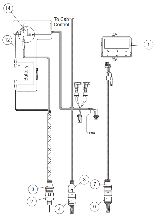 Fisher Plows Wiring Diagrams
 Fisher Plows Wiring Diagrams
 The Ultimate Guide to Understanding Fisher Plow Wiring Diagrams for 4
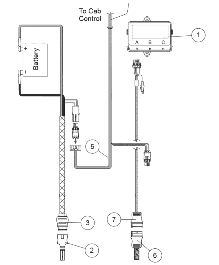 Fisher Plow 4 Port 3 Plug Wiring Diagram Wiring Diagram Western Snow
 Fisher Plow 4 Port 3 Plug Wiring Diagram Wiring Diagram Western Snow
 Fisher Plows Wiring Diagrams
 Fisher Plow Wiring Instructions
 Fisher Snow Plow Wiring Diagram - Wiring Diagram
 Wiring Harness Diagram For Fisher Plow 3 Plug

