2 SIDE PLOW LAMP P/T SIG HEADLAMP S1 SOLENOID S2 SOLENOID LT GRN LT BLU BLK/ORN WHT/YEL GRY BRN BRN RED RED #6 BLK . Fisher Engineering. No. 22372 2 1998 Contents . Wire Color Connector Identification charts diagrams give specific wire colors, function locations connectors. special notes are
 Configuration Plug Cavity Plug Wire Side View Secondary Lock C B Secure wires small terminals motor relay #10 lock washers 10-32 nuts. 5. Connect single-wire connector (black/orange wire) the vehicle control harness breakout the single-wire connector (black/orange wire) the vehicle cable assembly. not cable .
 16. Plug brown wire bullet connector black receptacle parking light circuit. Plug gray wire bullet connector black receptacle driver-side signal circuit. 17. Connect female spade terminal the small red wire the vehicle harness the male spade terminal the small red wire the vehicle battery cable.
 2. Insert cavity plug Position 3. Install secondary lock Headlamp Common = NEGATIVE (-) Headlamp Common = POSITIVE (+) insert terminal jumper wire position: 1. Push terminal correct cavity, 2. Listen a click. terminal pulls out, carefully bend locking tab outward reinstall terminal. Cavity Plug Wire Side View
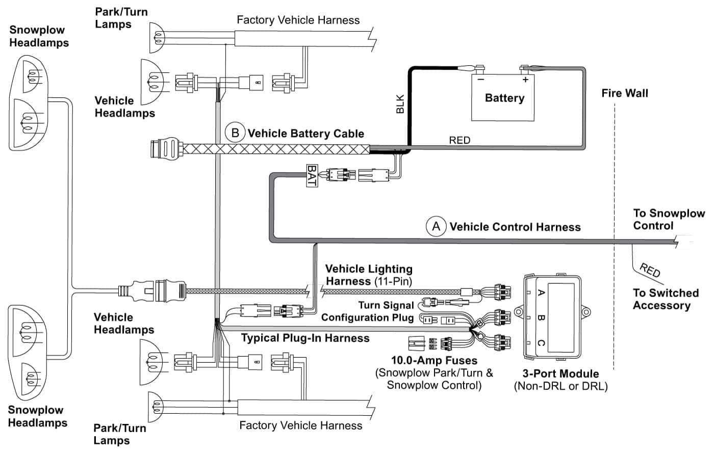
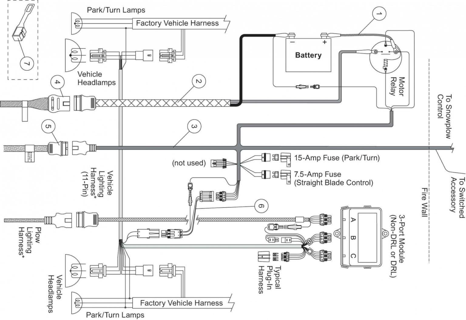
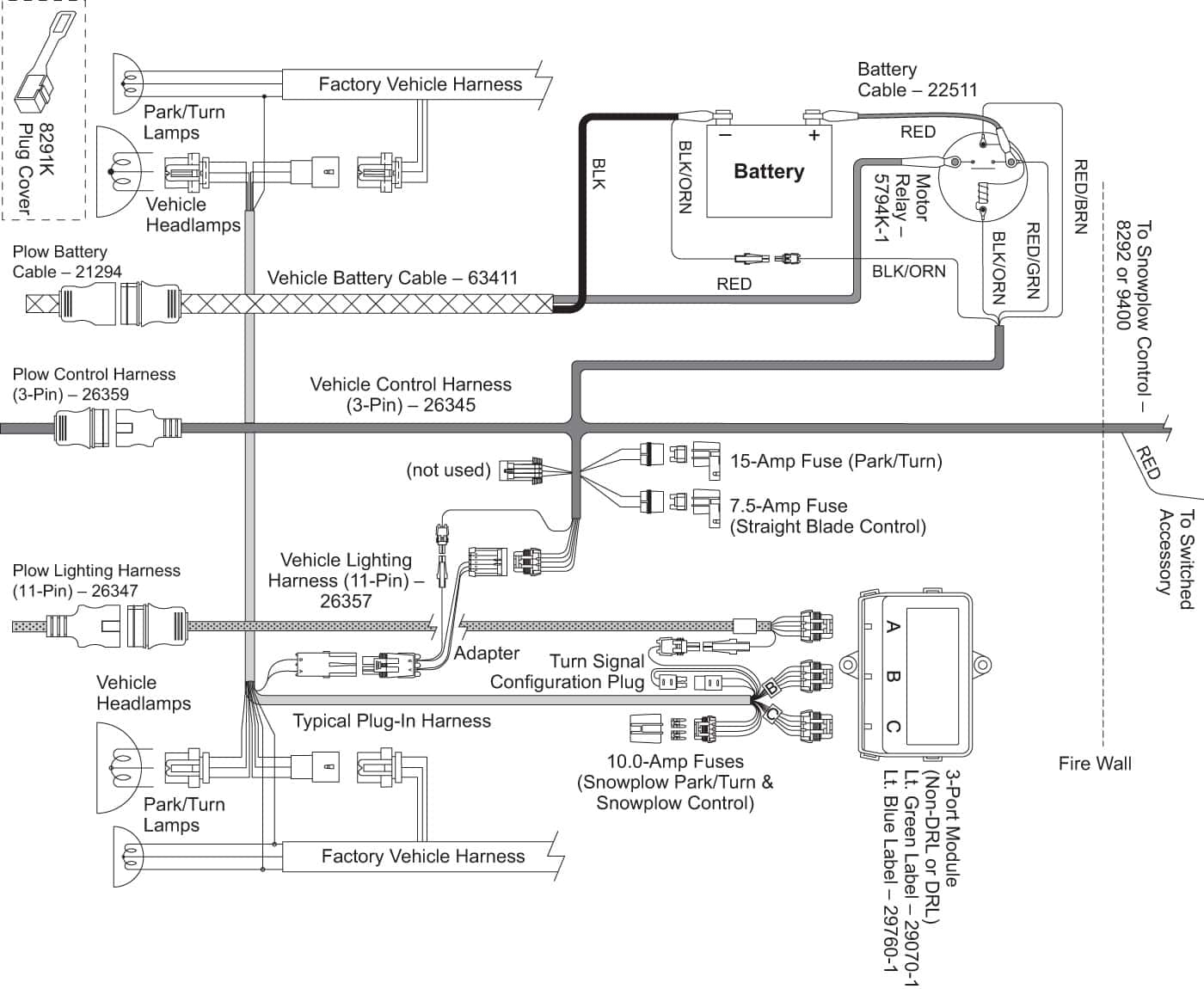
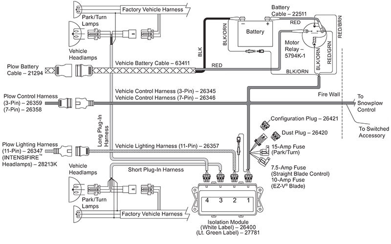
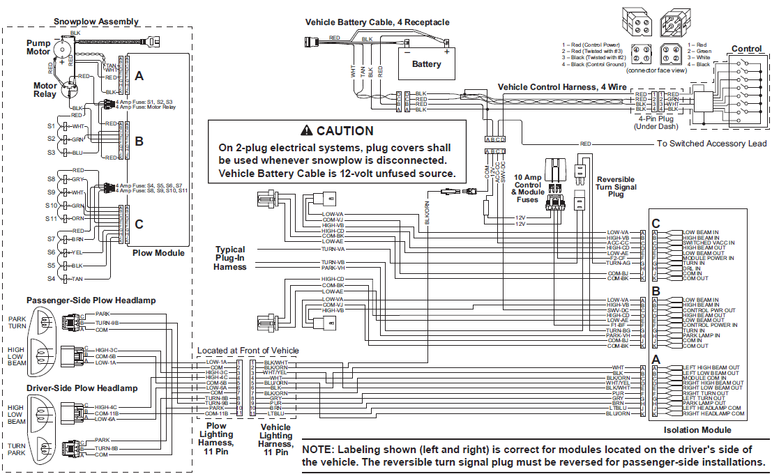 A Fisher 2 plug wiring diagram a schematic representation the electrical connections wiring configuration a Fisher snowplow a 2-plug system. Fisher snowplows commonly for clearing snow ice roads parking lots, the 2-plug system refers the main connectors to connect plow the vehicle .
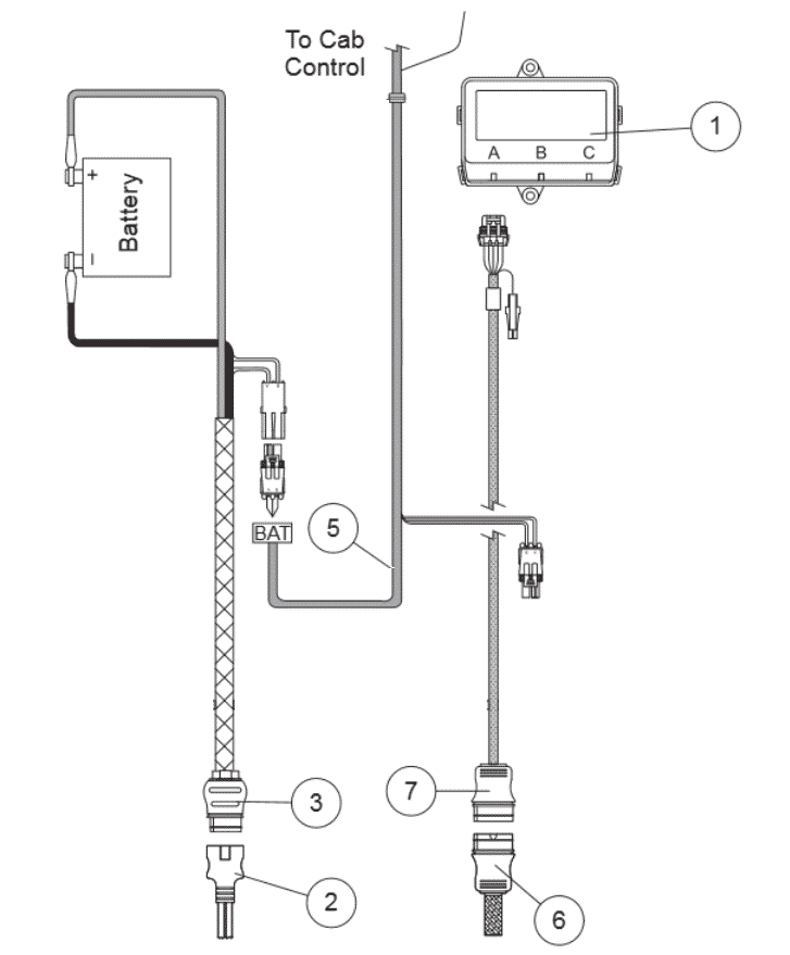
 The Fisher mm1 2 plug wiring diagram consists a set color-coded wires connect plow's electrical components the vehicle's electrical system. includes connections the control harness, power harness, hydraulic unit. . Fisher MM1 2 Plug System a snow plow attachment system designed use trucks. .
 ATTACHING/DETACHING SNOWPLOW VEHICLE HT Series™ ATTACH/DETACH DIAGRAM NOTE: each of snowplow, reapply dielectric grease the electrical plugs maintain protective coating the terminals. NOTE: Multiplexed 2-plug systems equipped plug covers. Headgear Push Bar Pin Release Handle (raised) Headlamp Bracket.
 The Fisher Plow 2 Plug wiring diagram a comprehensive guide helps understand wiring connections different components the plow system. provides detailed information how properly connect control module, harness, the solenoid the power source the electrical components the plow.

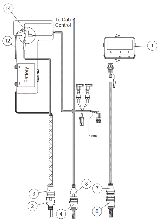 This my plow, I in desperate of help!! I have: * 98 Chevy K1500 Ext cab 5.7L * Older Fisher MM1 2 Plug system the headlight relays After days researching find wiring schematics wired the plow night. is wiring schematic found. light the joystick/controller lights up.
 Fisher Snow Plow Wiring Diagram - IOT Wiring Diagram
 Fisher Plow Wiring Diagram - Wiring Diagram
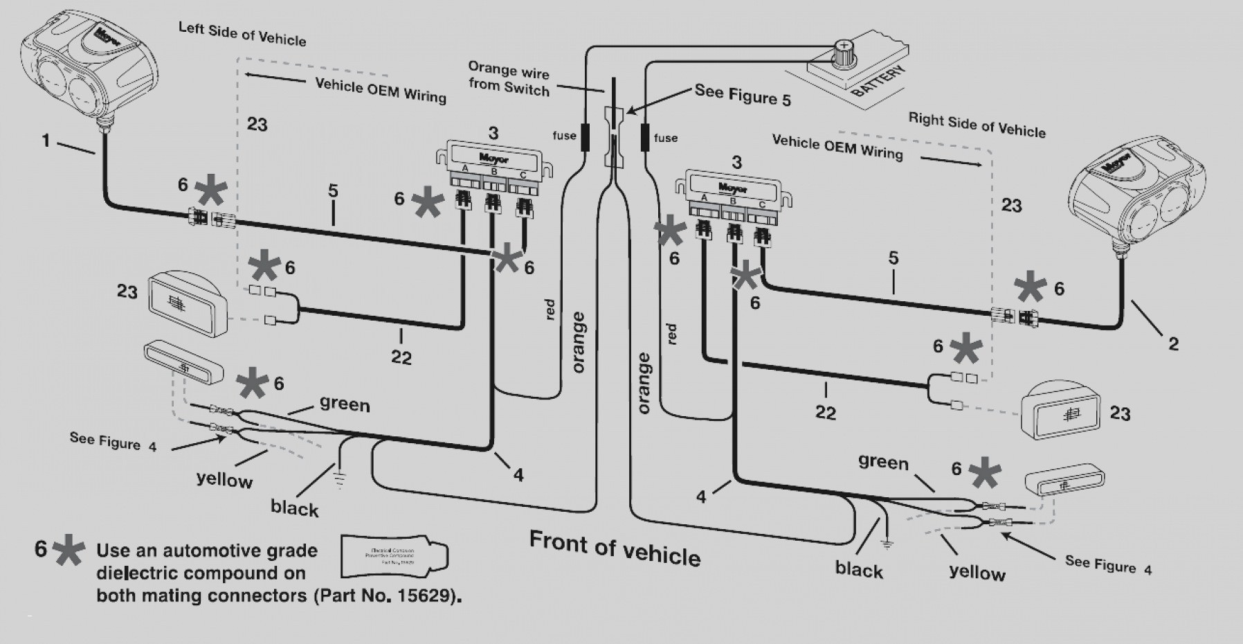 Fisher Minute Mount 2 Plow Wiring Schematic - Wiring Diagram
 Fisher Xv2 Plow Wiring Diagram
 How to Properly Wire a Fisher Snow Plow Controller: A Step-by-Step
 Fisher Plow 2 Plug Wiring Diagram

 The Ultimate Guide to Fisher Plow Relay Wiring: Tips, Tricks, and
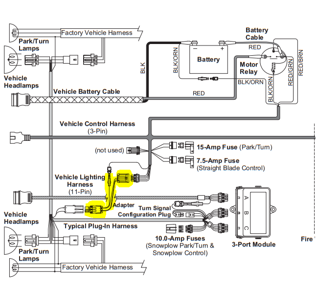

 Wiring diagram for Fisher 2 plug setup
