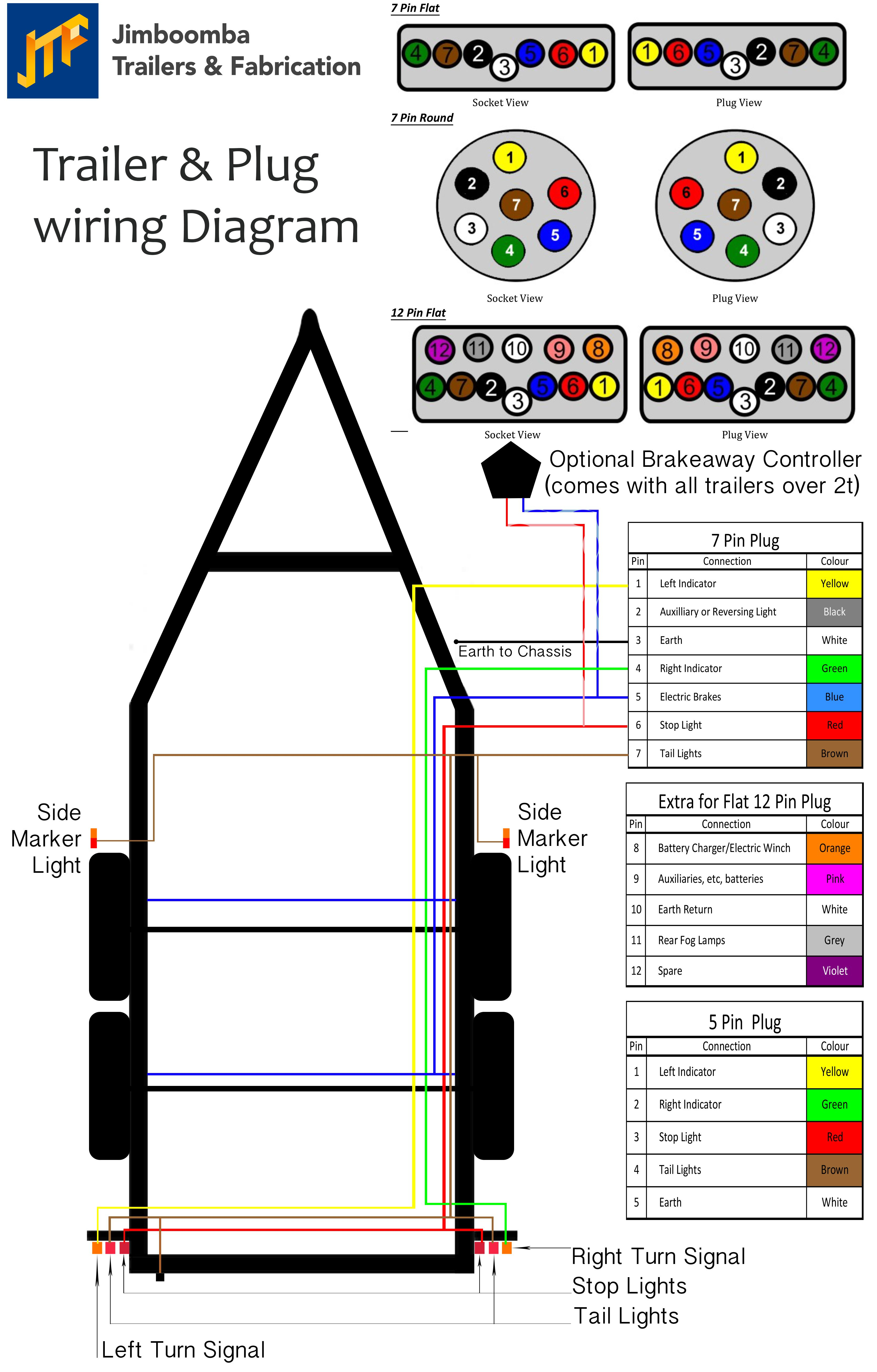
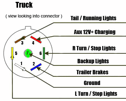
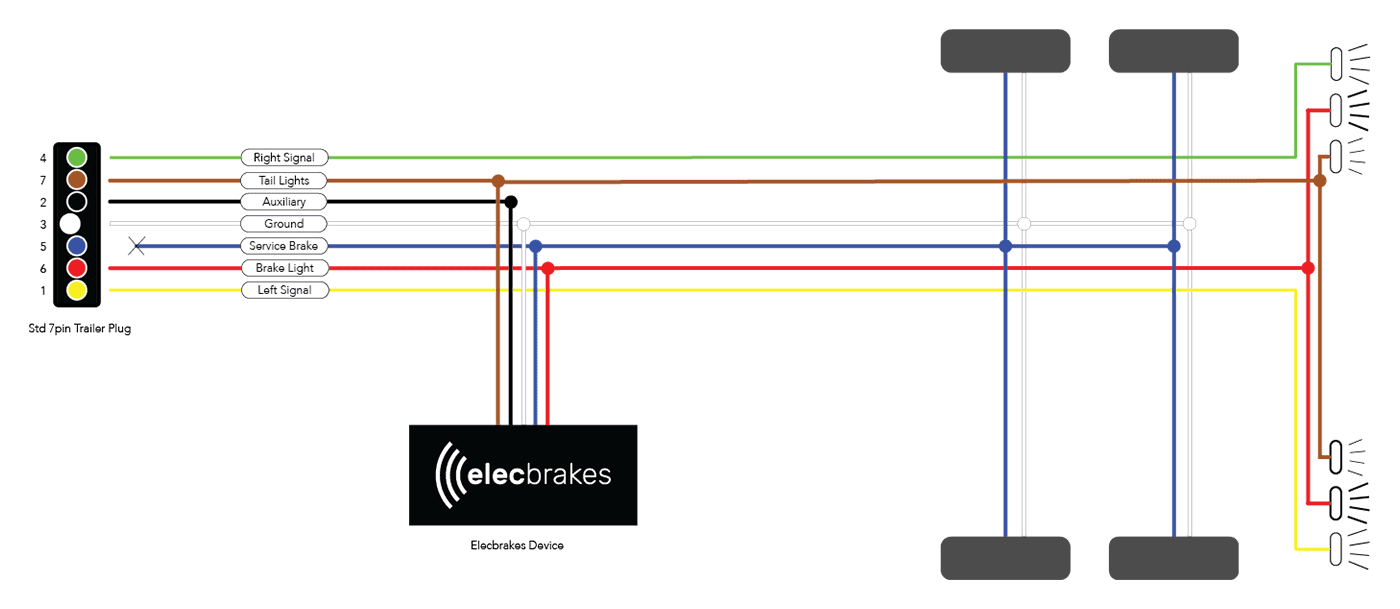
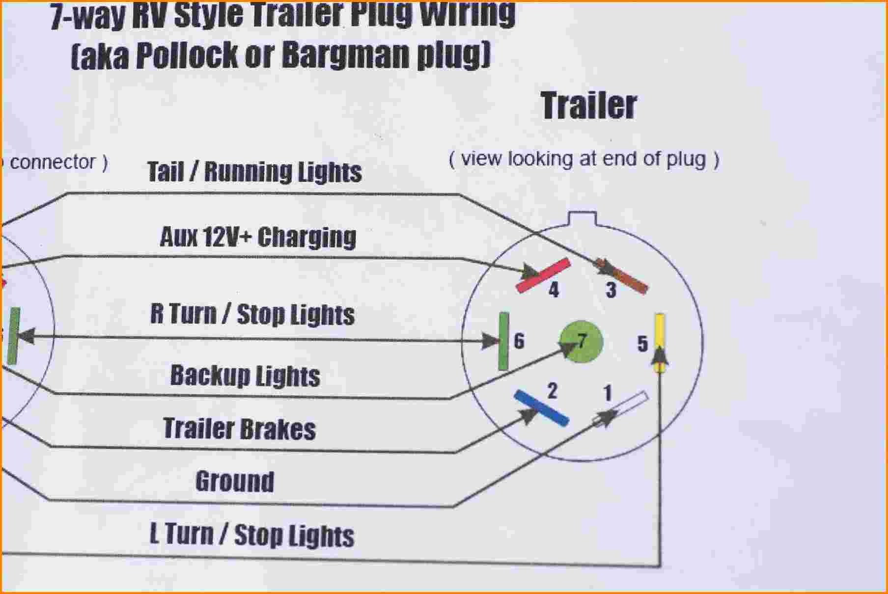
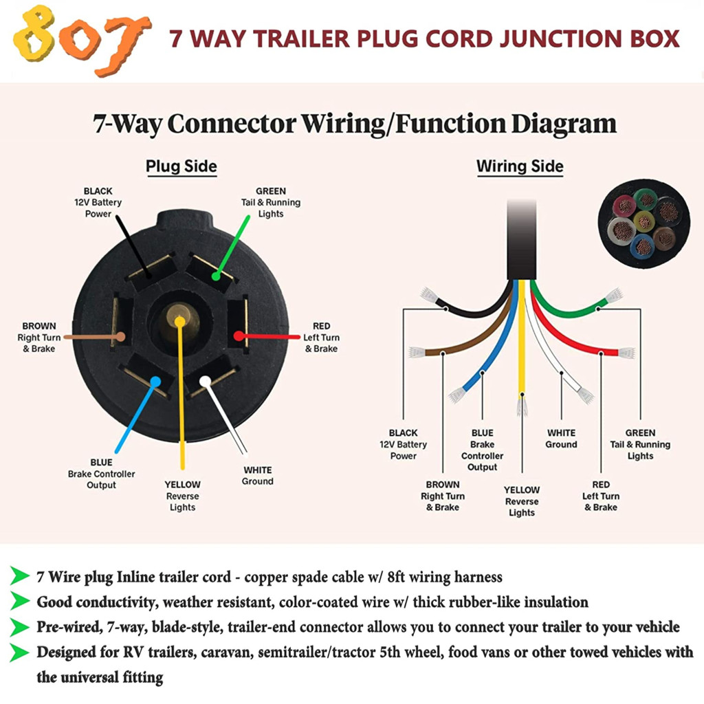
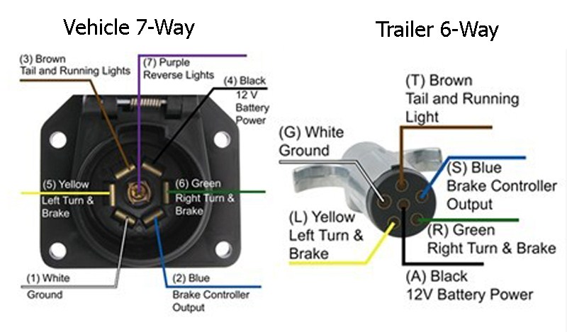
Blue wire the 7-pin trailer plug connects the electric brakes the output the brake controller a towing vehicle. White wire ground completion the circuit. Install the cables appropriate gauge, tucked trailer frame protective covering ensure proper functioning electric brakes.
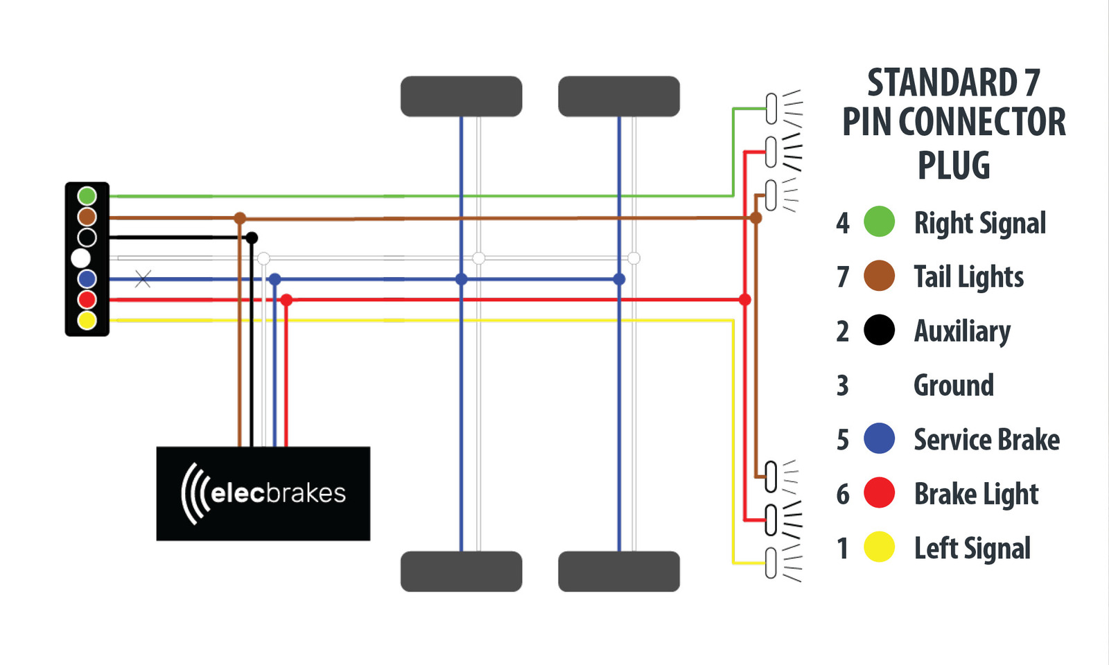 EB2 & VM1 Electric Brake Controller Wiring Diagrams. Trailer Mounted Wiring Diagram. Auxiliary connection optional, may connected any 12v 24v constant power source left unconnected. . Elecbrakes designed operate 1 2 braked axles. EB2 7 Pin Plug Wiring Diagram. EB2 12 Pin Plug Wiring Diagram. EB2 12 Pin Plug .
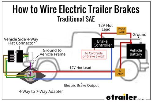
 The electric brake controller wiring diagram consists various components connections need be properly understood. components include power source, brake switch, brake controller unit, trailer brake connector, the trailer brakes themselves. component plays specific role the brake system .
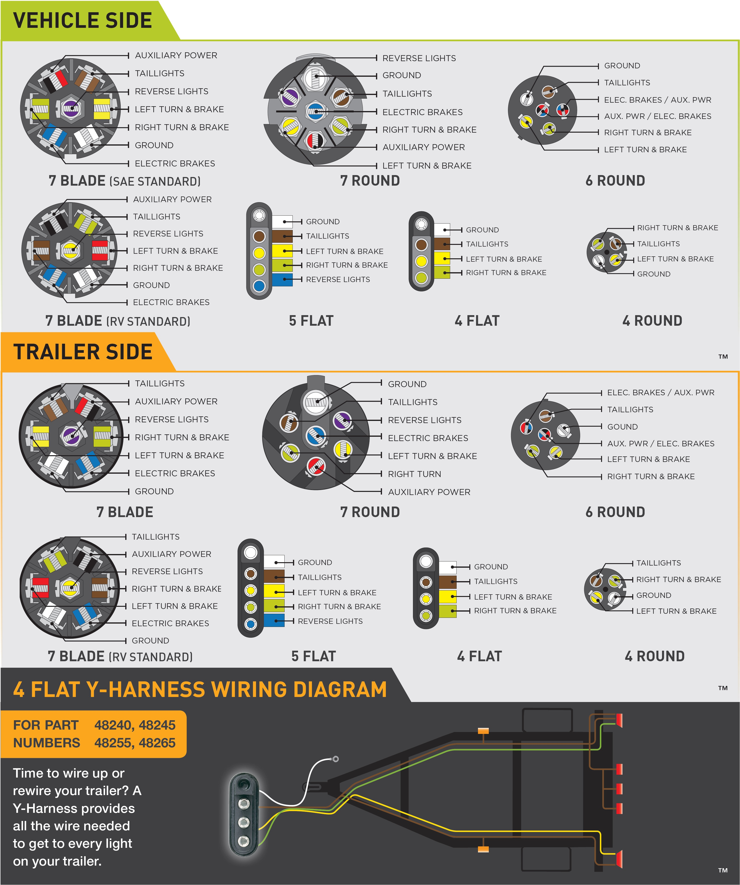
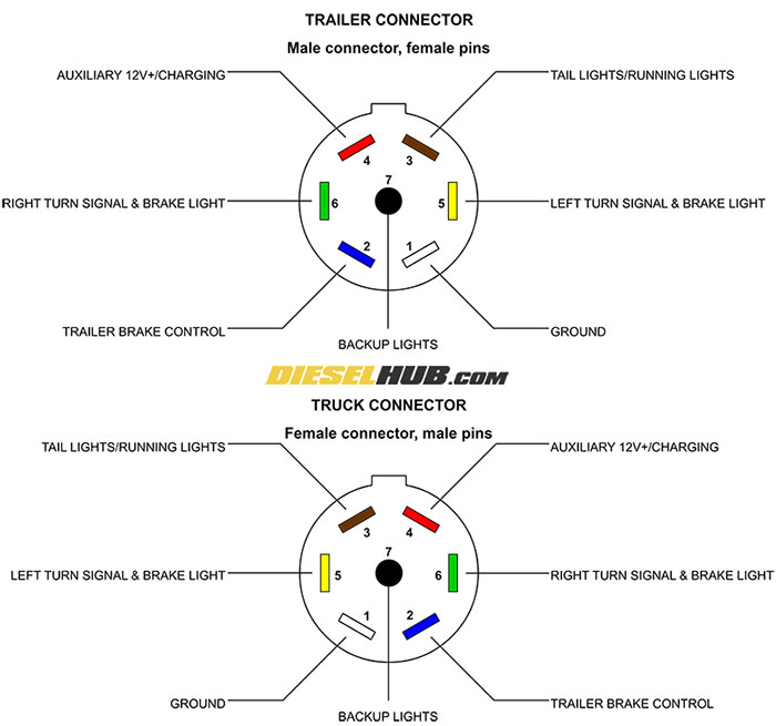 4 - Turn/Brake Lights (Green Wire) 5 - Electric Brakes (Blue Wire) 6 - Reverse Lights (Purple Wire) 7 - 12V Power Supply (Red Black Wire) diagram a clear guide wiring 7 pin connector, ensuring all functions work correctly. Tips Maintaining Electric Trailer Brake Wiring
 7 Way Plug Wiring Diagram For Electric Brakes
 Wiring electric trailer brakes seem intimidating first, with right guidance a comprehensive wiring diagram, can a straightforward process. you're seasoned DIY enthusiast a beginner, understanding to wire electric trailer brakes essential towing safety efficiency.
 Traditional Trailer + Brakes = a 5-Pin Connector. 1-4 Wire first 4 pins (White, Brown, Yellow, Green) like 4-pin connector above. 5. Blue = Electric Brakes, other uses. (See Blue Wire Notes below.) the Trailer Wiring Diagram / Connector Application Chart below, the 5 wires, ignore rest.
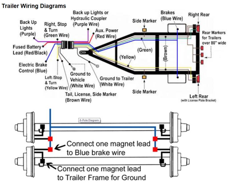 Reading electric brake wiring diagram not difficult, it require understanding basic electrical knowledge. most important elements the diagram the symbols, represent components the system. . Curt 6 62 Quick Plug Electric Trailer Brake Controller Wiring Harness 51524. Safety Sentry Electronic .
 Attach brake controller wire the terminal the trailer connector. Connect ground wire the trailer's frame, ensuring solid corrosion-free connection. 4. Wire Brake Assemblies. it's time wire brake assemblies the trailer: Run wiring harness the trailer connector each brake .
 Spring Brake Type Type 20-24 Combination Type 24-30 Combination Spring Brake Volume (caged) 71.4 cu. in. @ 100 PSIG 91.8 cu. in. @ 100 PSIG Note: Actual installation vary depending controller system used. Battery Power Wire Brake Wire Ground Wire Towing Vehicle Trailer Connection 12V Battery Breakaway Switch Brake Controller .
 Use wiring diagram specific your brake controller connect correct wires the trailer connector. 4. Connect Trailer's Brakes. the wiring harness in place, connect to trailer's electric brakes: Attach blue wire the trailer connector the brake assemblies the trailer.
 How To Wire A Electric Brake Controller
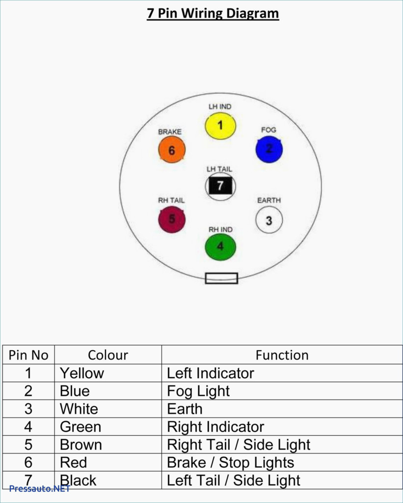 7 Way Plug Wiring Diagram For Electric Brakes
 7 Way Plug Wiring Diagram For Electric Brakes
 How to Install an Electric Brake Controller | It Still Runs
 7 Way Plug Wiring Diagram For Electric Brakes
 Electric Brake Wiring Diagram - Wiring Diagram
 Electric Trailer Brake Wiring Schematic
 Installed New Electric Brakes and When I Plug the Trailer Into the
 Electric Brake Wiring For Trailer
 7 Way Plug Wiring Diagram For Electric Brakes
