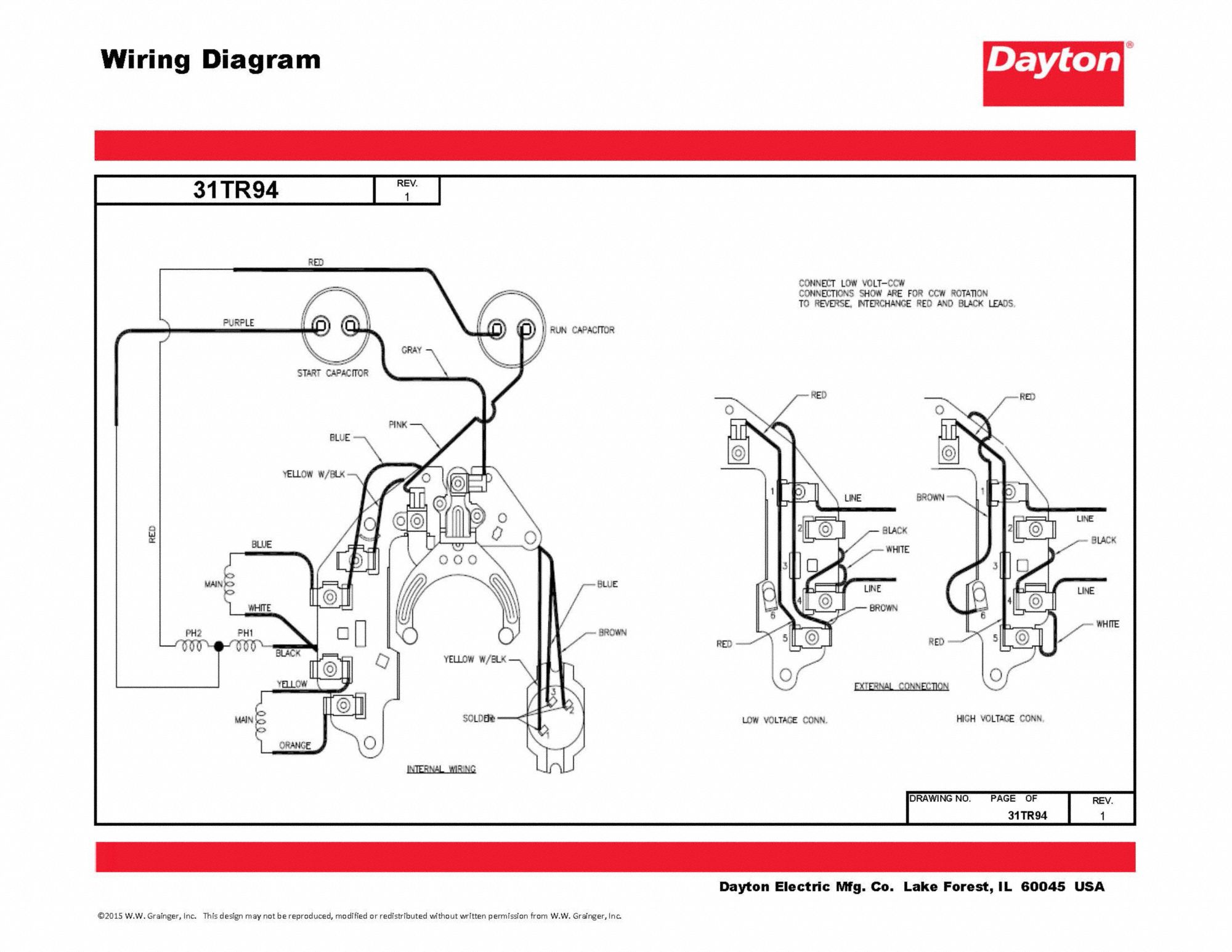
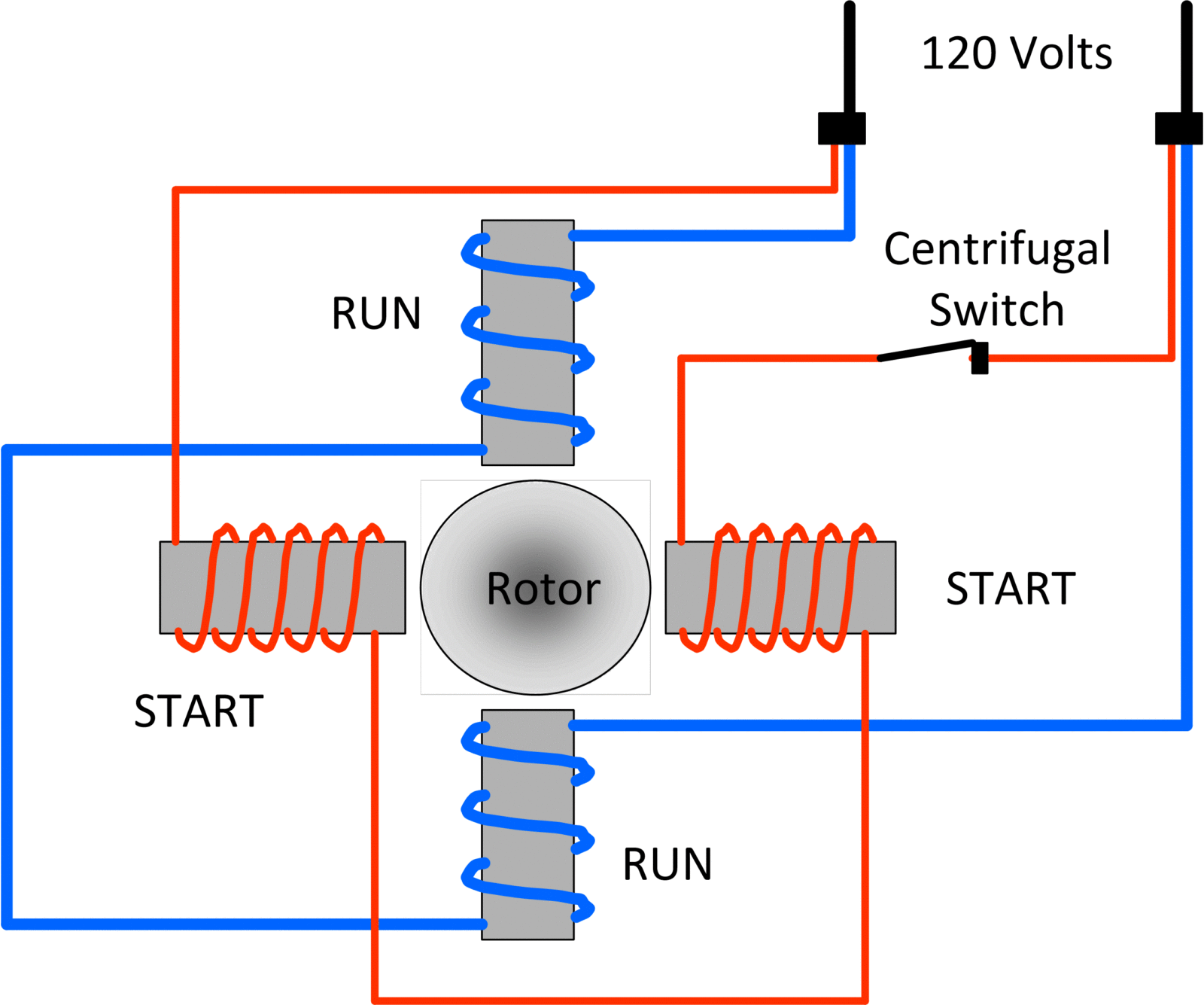
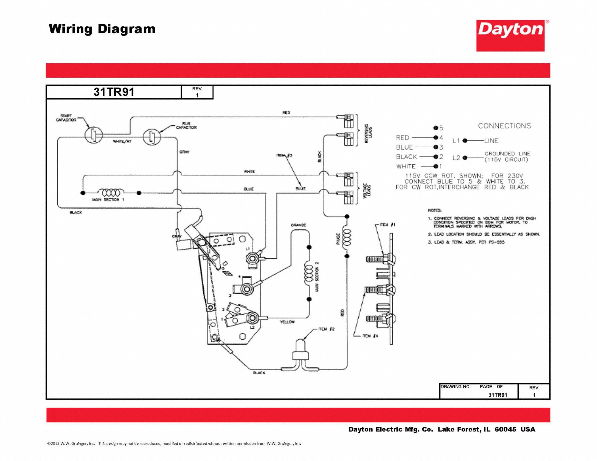
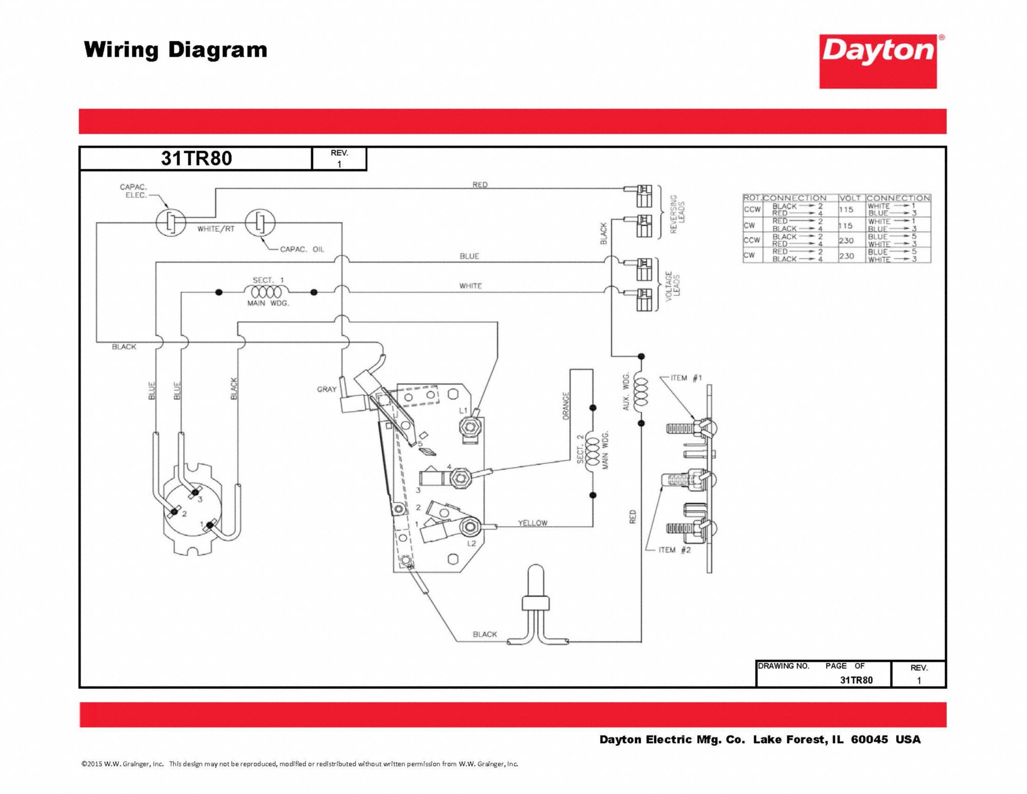
The wiring diagram a Dayton split phase motor typically consists a diagrammatic representation the motor's terminals, labeled T1, T2, T3, the connections the power supply, labeled L1 L2. diagram includes start winding, is connected the capacitor, the auxiliary winding, helps .
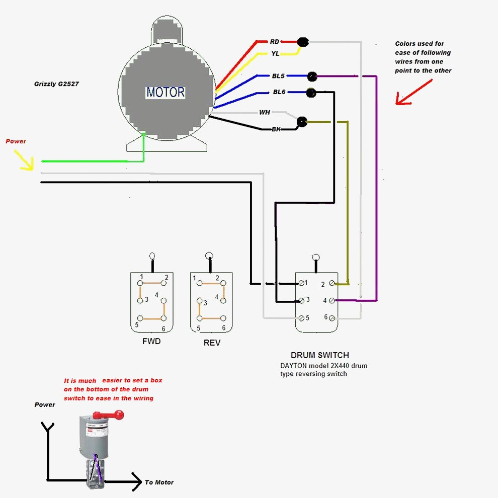
 Wiring Reversable Motor Dayton Drum Switch Home Model Engine Machinist Forum. Electrical Diagram A Csir Motor. Dayton Gp Motor 1 3 Hp 725 Rpm 115 208 230v 5k121 Com. Diagram Page. 2 Sd Motor Wiring A Guru Pre 1950 Antique Fan Collectors Association Afca Forums. Dayton General Purpose Motor Totally Enclosed Fan Cooled Rigid Base .
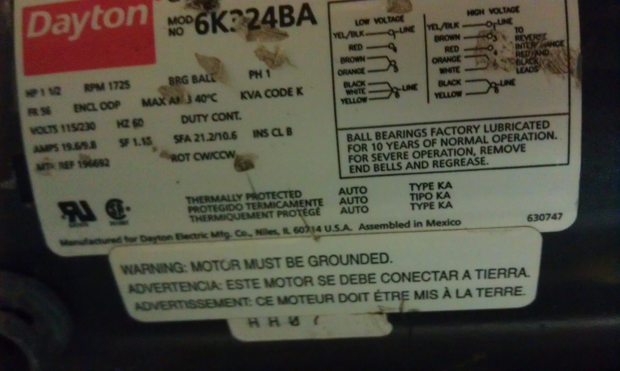
 To connect motor proper voltage rotation, refer the connection diagram the nameplate inside terminal/conduit box. Table B - Minimum Wire Sizes Single-Phase Motors Motor — 25 Feet — — 50 Feet — — 100 Feet — — 150 Feet — — 200 Feet — HP 115V 230V 115V 230V 115V 230V 115V 230V 115V 230V
 Dayton Split Phase Motor Wiring
 Dayton ® Split Phase Gearmotors Refer Form 8S707 Safety Installation, Operation Maintenance Instructions . Wiring Diagram Reverse Interchange Red Black Motor Leads Reassembly Instructions 1. Assemble rotor stator . 1 AC MOTOR P155-541-0003 P155-541-0003 P155-541-0003 P155-541-0003 1
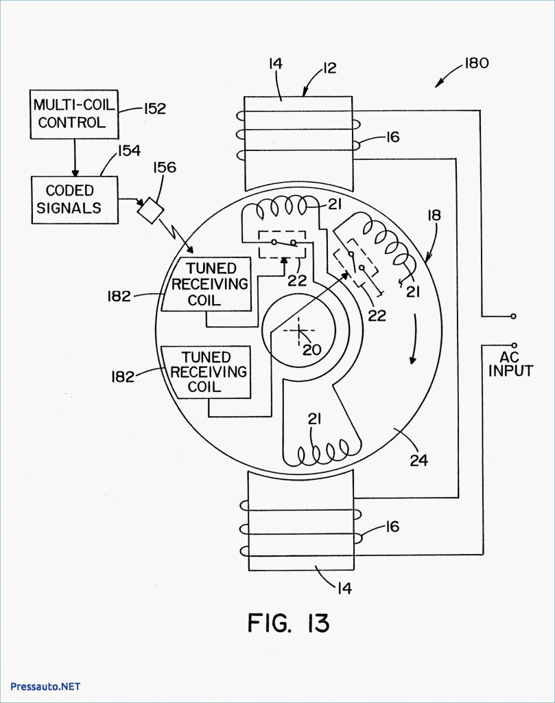 Dayton ® Split Phase Gearmotors Refer Form 8S707 Safety Installation, Operation Maintenance Instructions . Wiring Diagram Reverse Interchange Red Black Motor Leads Reassembly Instructions 1. Assemble rotor stator . 1 AC MOTOR 1/2 HP P150-541-1003 P150-541-1003 P150-541-1003 1
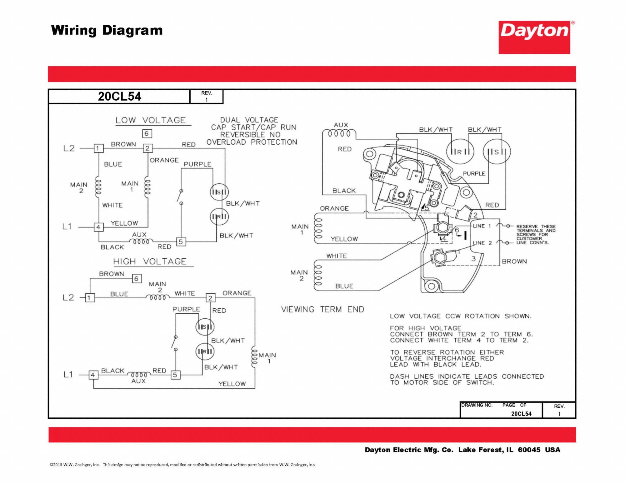
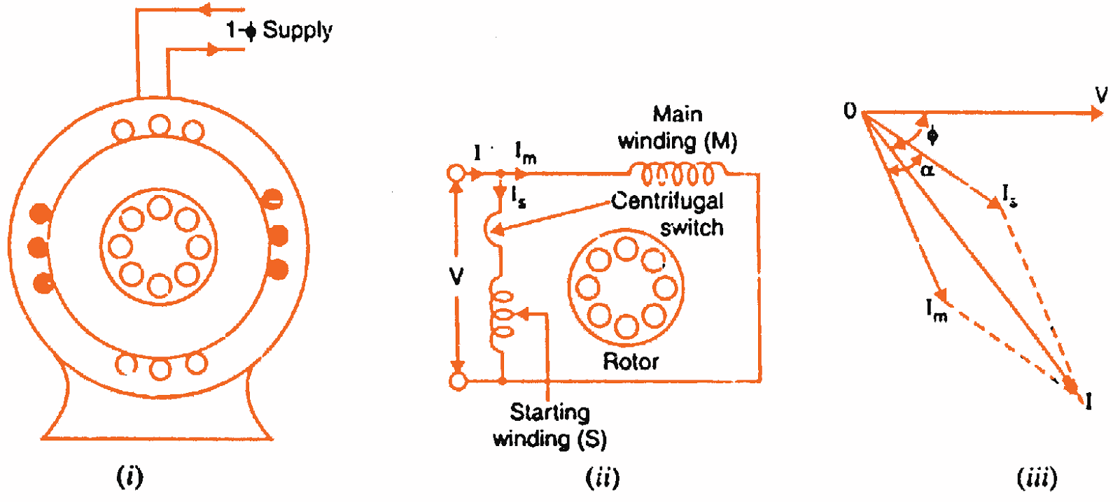.png) Understanding Dayton Electric Motors Wiring Diagrams. . Dayton High Torque Farm Duty Motor Capacitor Start Run 5 Hp 230v Ac 1 740 Nameplate Rpm 182 4t Frame 6k847 Zoro. Drum Switch Wiring Split Phase Motor Hobby Machinist.
Understanding Dayton Electric Motors Wiring Diagrams. . Dayton High Torque Farm Duty Motor Capacitor Start Run 5 Hp 230v Ac 1 740 Nameplate Rpm 182 4t Frame 6k847 Zoro. Drum Switch Wiring Split Phase Motor Hobby Machinist.
 Wiring Diagram Reverse Interchange C7 Red C1 Black Motor Leads Reassembly Instructions . Dayton ® Split Phase Gearmotors Refer Form 8S707 Safety Installation, Operation Maintenance Instructions . 1 AC MOTOR 1/2 HP P150- 541-1003 P150--1003 1
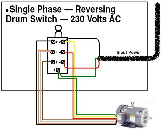
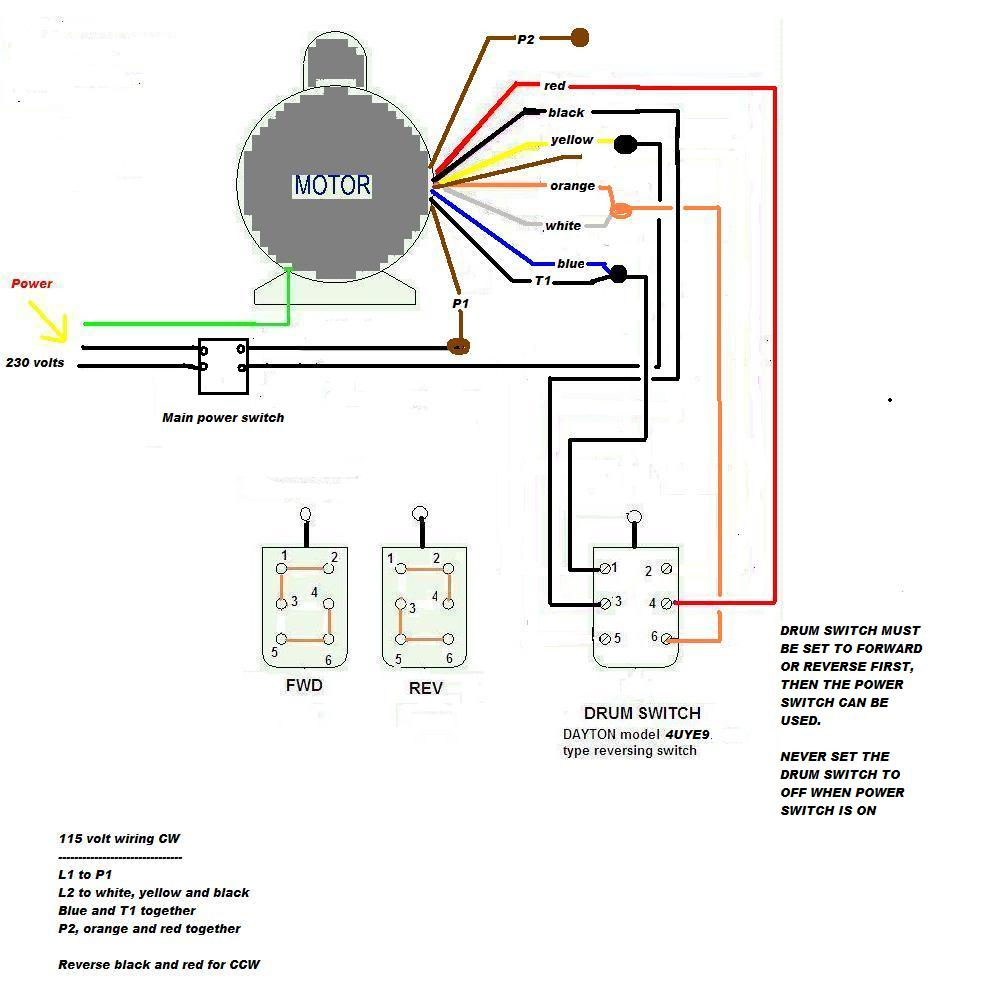
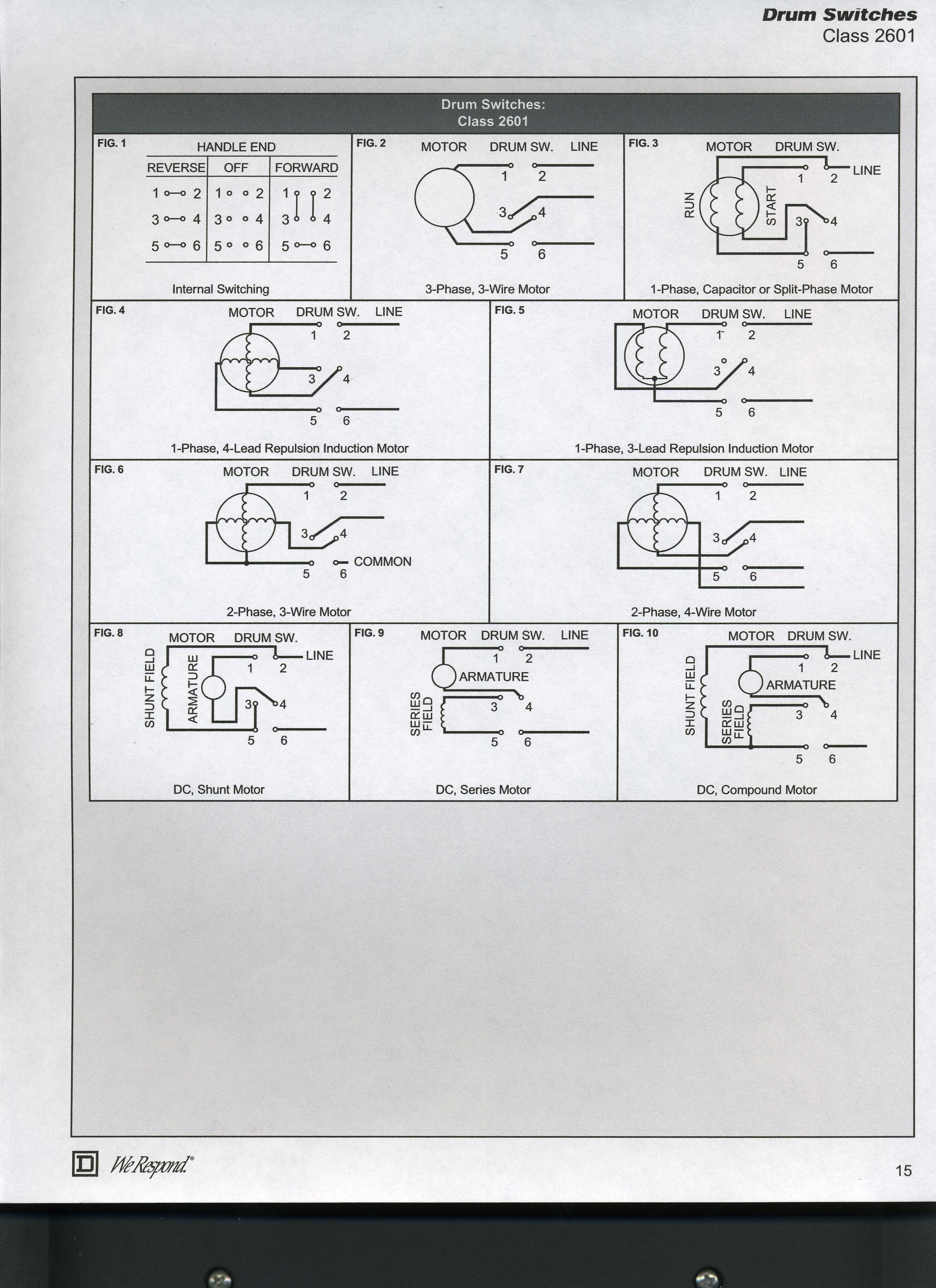
 first all need choose diagram the motor you intend use how connects F R motor labeled split phase, use diagram labeled split phase switch :: 1 2 connect F R 5 6 connect F R F:: 3 connects 1 2 4 connects 5 6
 Therefore the exact wiring diagram the motor OP are 3 options. (1) wire drum switch reverse Red Black their shown connections wire motor 120VAC. (2) Connect Red Black as (1) wire motor 240VAC switch on/off one side the 240VAC line.
 Dayton Split Phase Motor Wiring Diagram Wiring Diagram | Images and
 Dayton Electric Motor Wiring Diagrams
 Dayton Electric Motors Wiring Diagrams
 Dayton Wiring Diagrams
 Dayton Split Phase Motor Wiring Diagram
 Understanding Dayton Motor Wiring Schematic - A Complete Guide
 Dayton Single Phase Wiring Diagram
 Understanding Dayton Motor Wiring Schematic - A Complete Guide
