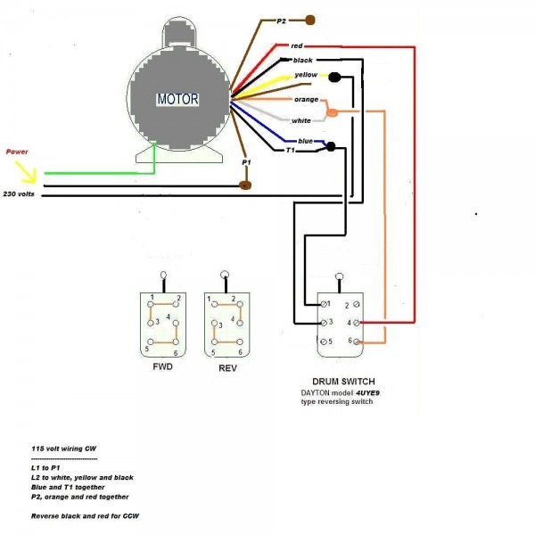
Three-Phase Motor Wiring: Century three-phase AC motors commonly in larger industrial applications. motors three main winding connections: A phase, B phase, C phase. wiring diagram a three-phase motor show specific connections each phase, typically labeled T1, T2, T3, sometimes T4.
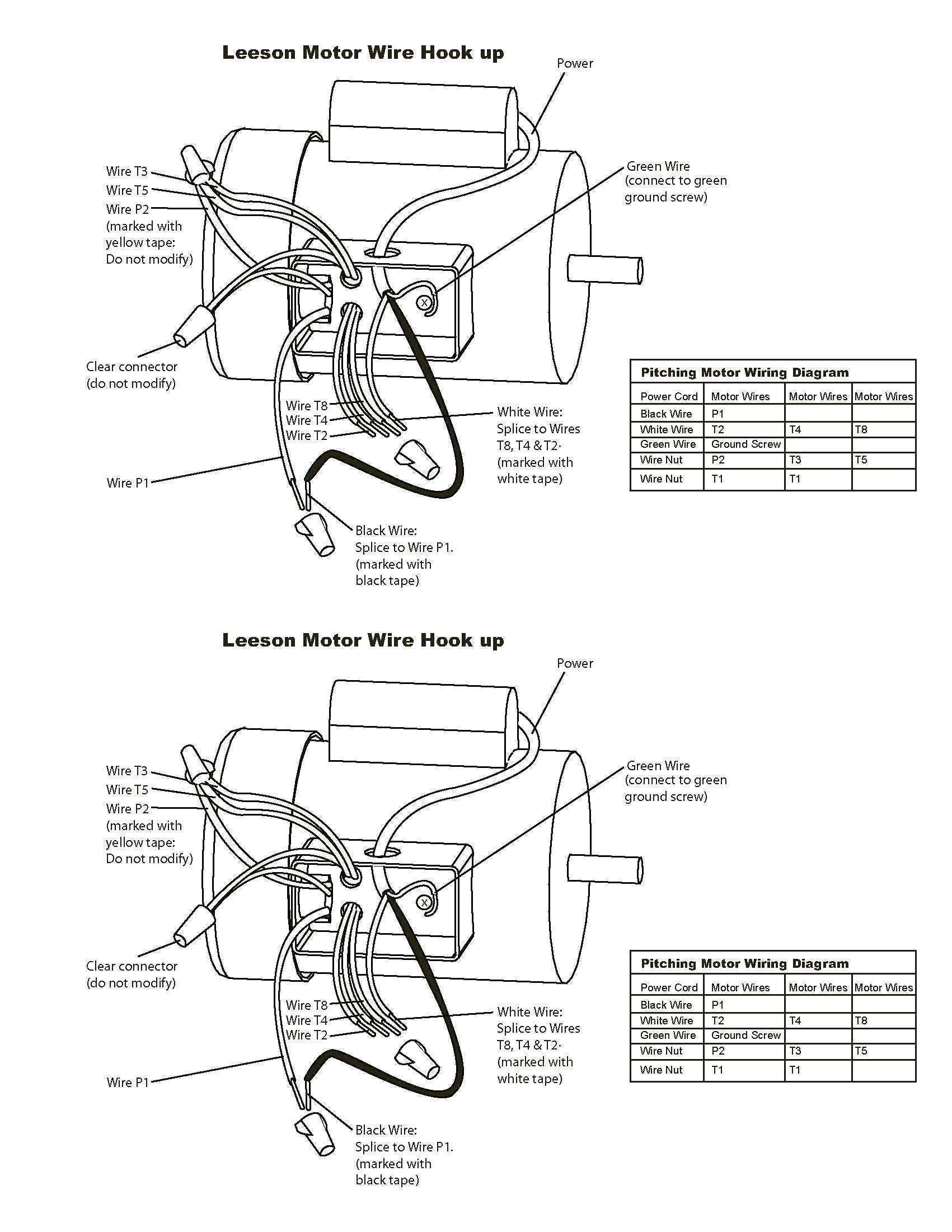
 A Century pump motor wiring diagram a visual representation the electrical connections components involved the motor's operation. outlines various terminals, wires, connections, allowing to understand circuitry make necessary connections. . as 115/230 volts single-phase three-phase. .
 8.PH (Phase): Denotes single- three-phase motor. 9.SF (Service Factor):Service factor the measure the reserve margin built a motor. Motors rated 1.0 SF the motor operate a higher margin designated the horsepower rating. Maximum horsepower capability equals horsepower multiplied the SF. (continuous .
 Connect "Brown" motor lead the #3 terminal a 230-volt hookup to #5 terminal a 115-volt hookup. connect Brown motor lead the terminal for line voltage used the motor. a male/female push-on connector a ring terminal secured a terminal post a nut connects brown wire.
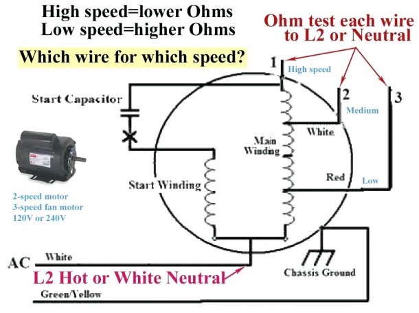 8 . PH (Phase): Denotes single- three-phase o o . 9 . SF (Service Factor): e vice factor the measure the s r ve margin built a motor. Motors rated 1.0 SF the motor operate a higher margin designated the horsepower rating. Maximum horsepower capability equals horsepower multiplied the SF.
 Century Electric Motor Wiring Diagram Jump page : 1 viewing page 1 [50 messages page] View previous thread:: View thread Forums List-> Machinery Talk: . 3 phase motors be wired 240 480 volts. low voltage tie 1 7, 2 8 3 9, 4 5 6 tied together. .
 How Read Century Electric Motors Wiring Diagram. Century Electric Motors wiring diagrams sometimes daunting, with little guidance, can easily understood interpreted. is crucial become familiar the symbols components in diagram ensure proper installation troubleshooting. key .
 Single Phase Terminal Markings Identified Color: (NEMA Standards) 1-Blue 5-Black P1-No color assigned 2-White 6-No color assigned P2-Brown 3-Orange 7-No color assigned 4-Yellow 8-Red . Phase Connections: Part Winding Start:
 The 3 phase wiring diagram motors typically includes information as voltage current ratings, type motor (e.g., induction motor synchronous motor), the connection details. is crucial follow correct wiring diagram ensure motor wired correctly, an incorrect connection lead motor .
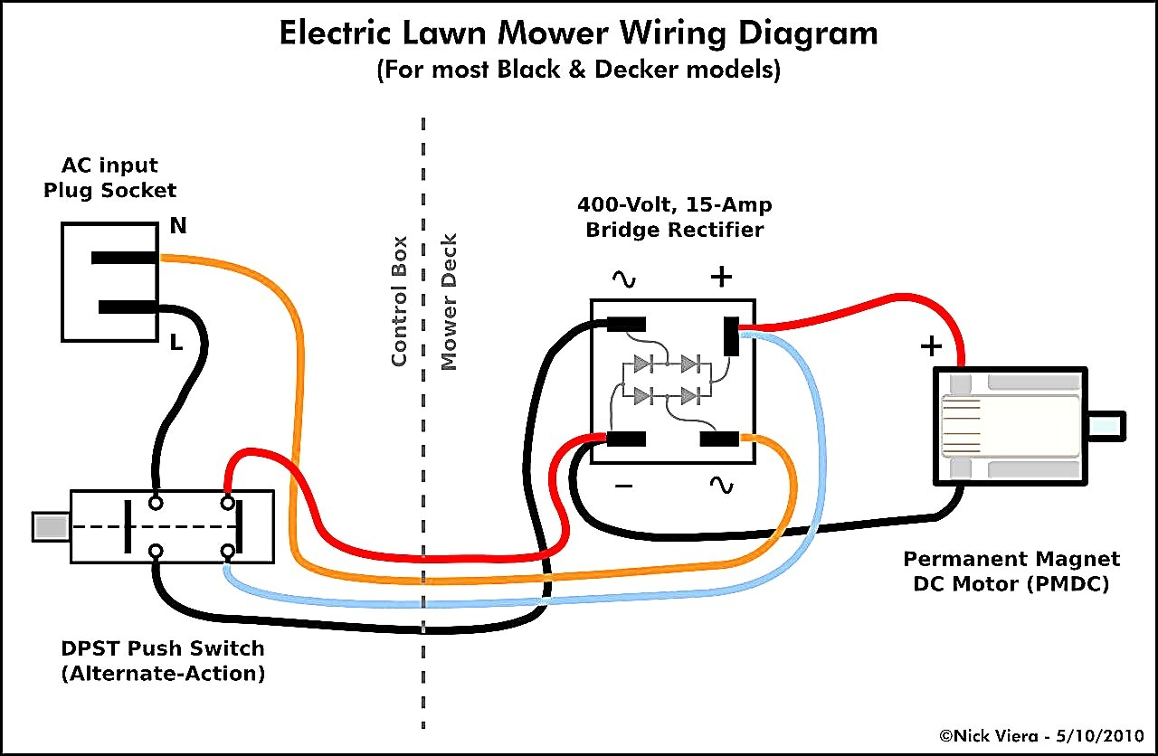 Wiring errors result costly repairs even serious problems. Thankfully, wiring AC motor straightforward doesn't require lot effort. century AC motor wiring diagram provide clear instructions connecting single-phase motor a three-phase motor a 230-volt power source.
 Schematic Diagram Of Three Phase Motor
 Century Motor Wiring Diagram - Collection - Wiring Collection
 Century Ac Motor Wiring Diagram 115 230 Volts - Wiring Diagram
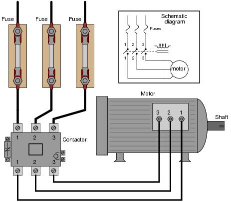 3 Phase Motors Wiring
 Ac Motor Speed Picture: Century Ac Motor Wiring
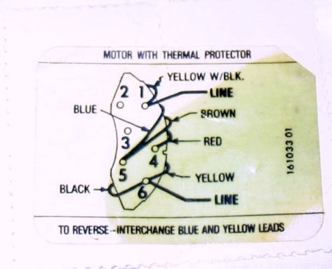 Century B969 Motor Wiring Diagram 2 Speed Motor Wiring Motor
 Century Electric Motors Wiring Diagram
 Electric Motor Wiring Diagrams 3 Phase
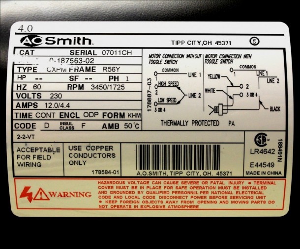 Century 3 4 Hp Motor Wiring
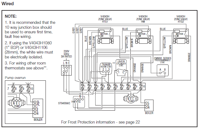 Century Motor B813 Wiring Diagram
 Schematic Diagram Of Three Phase Motor
