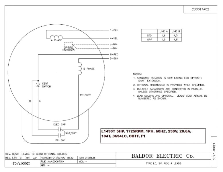
The wiring diagram a Baldor single phase motor with capacitor typically includes key components, including main power source, capacitor, start winding, the run winding. capacitor connected both start run windings helps provide necessary electrical energy start motor keep .
 However, a simplified guide the Baldor single phase wiring diagram, can easily navigate intricacies wiring motor. Baldor single phase wiring diagram a visual representation how different components your motor connected. shows placement wires, terminals, other electrical connections.
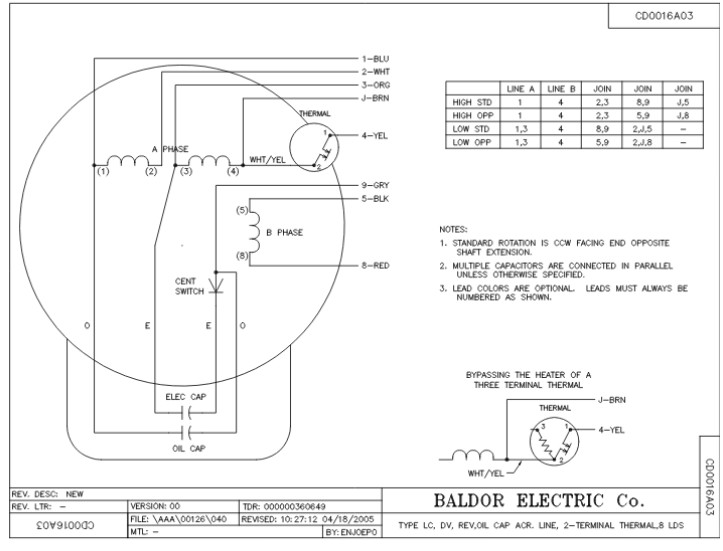 Understanding wiring single phase motors crucial proper installation troubleshooting. wiring diagram in guide illustrates connections required power 5hp Baldor single phase motor. includes necessary components, as start run windings, centrifugal switch, the power source.

 This motor be installed accordance National Electric Code, NEMA MG-2, IEC standards local codes. WIRING Connect motor shown the connection diagrams. this motor installed part a motor control drive system, connect protect motor to control manufacturers diagrams.
 They produce wide range motors, including single-phase three-phase motors, are in industries as HVAC, automotive, agriculture. . ensure proper installation wiring, is recommended consult Baldor motor wiring diagram the motor's installation manual. resources provide step-by-step .
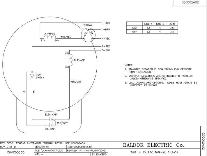 This diagram detailed information how connect motor the power source, including wires connect specific terminals. is important carefully follow diagram ensure correct wiring to avoid damaging motor. Steps wire Baldor single phase motor:

 A Baldor single phase motor wiring diagram with capacitor a great tool DIYers want get motors and running quickly safely. you're to replace old motor just to understand to correctly wire new one, guide walk through process step-by-step. .
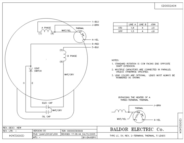
 This guide help understand different symbols connections in Baldor motor wiring diagrams, allowing to troubleshoot repair electrical issues your motor. . Single-phase Motors: Baldor single-phase motors widely in residential small commercial applications, offering simplicity cost-effectiveness.
 Baldor 5hp Single Phase Motor Wiring Diagram - Wiring Diagram
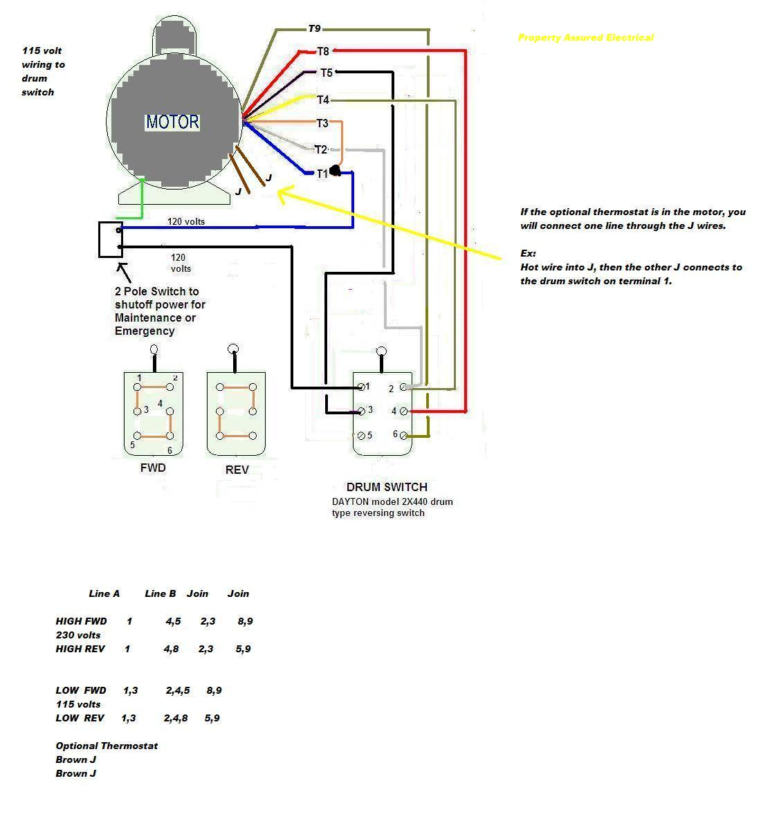 Baldor Motor Wiring Diagrams 1 Phase
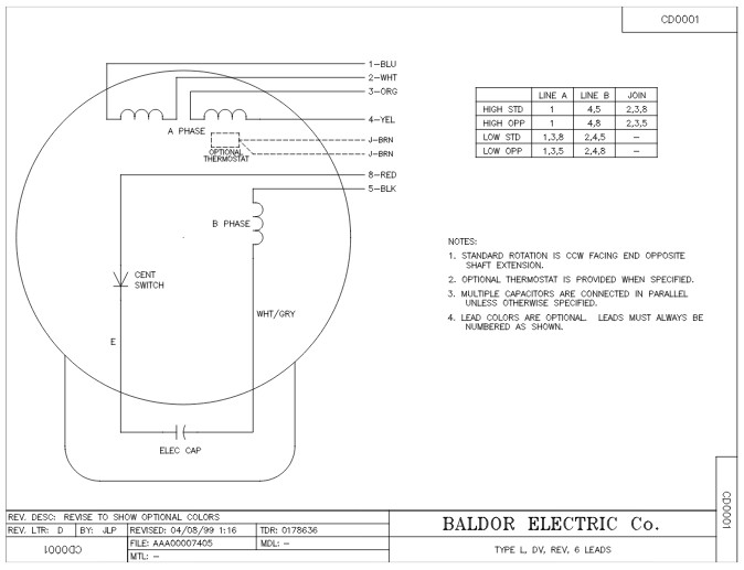 Baldor Single Phase 230v Motor Wiring Diagram - Wiring Diagram
 Baldor Motor Wiring Diagrams Single Phase
![[DIAGRAM] Wiring Diagram Baldor 2 Hp Single Phase Motor - MYDIAGRAMONLINE [DIAGRAM] Wiring Diagram Baldor 2 Hp Single Phase Motor - MYDIAGRAMONLINE](https://www.gghyd.com/media/catalog/product/l/1/l1408t-baldor-single-phase-open-foot-mounted-3hp-1725rpm-184t-frame-upc-781568101605-3.jpg) [DIAGRAM] Wiring Diagram Baldor 2 Hp Single Phase Motor - MYDIAGRAMONLINE
[DIAGRAM] Wiring Diagram Baldor 2 Hp Single Phase Motor - MYDIAGRAMONLINE
![[DIAGRAM] Baldor Single Phase Motor Wiring Diagrams - MYDIAGRAMONLINE [DIAGRAM] Baldor Single Phase Motor Wiring Diagrams - MYDIAGRAMONLINE](https://1.bp.blogspot.com/-7WPC0-DJ4Hg/WOvKdkOZmRI/AAAAAAAABHw/jW0YUU-fUJUdzkgGMH-EAc03UQ5gJgAwgCLcB/s1600/Single%2BPhase%2BMotor%2BWiring%2BDiagram%2BWith%2BCircuit%2BBreaker.jpg) [DIAGRAM] Baldor Single Phase Motor Wiring Diagrams - MYDIAGRAMONLINE
[DIAGRAM] Baldor Single Phase Motor Wiring Diagrams - MYDIAGRAMONLINE
 baldor 5hp single phase motor capacitor wiring diagram - Wiring Diagram
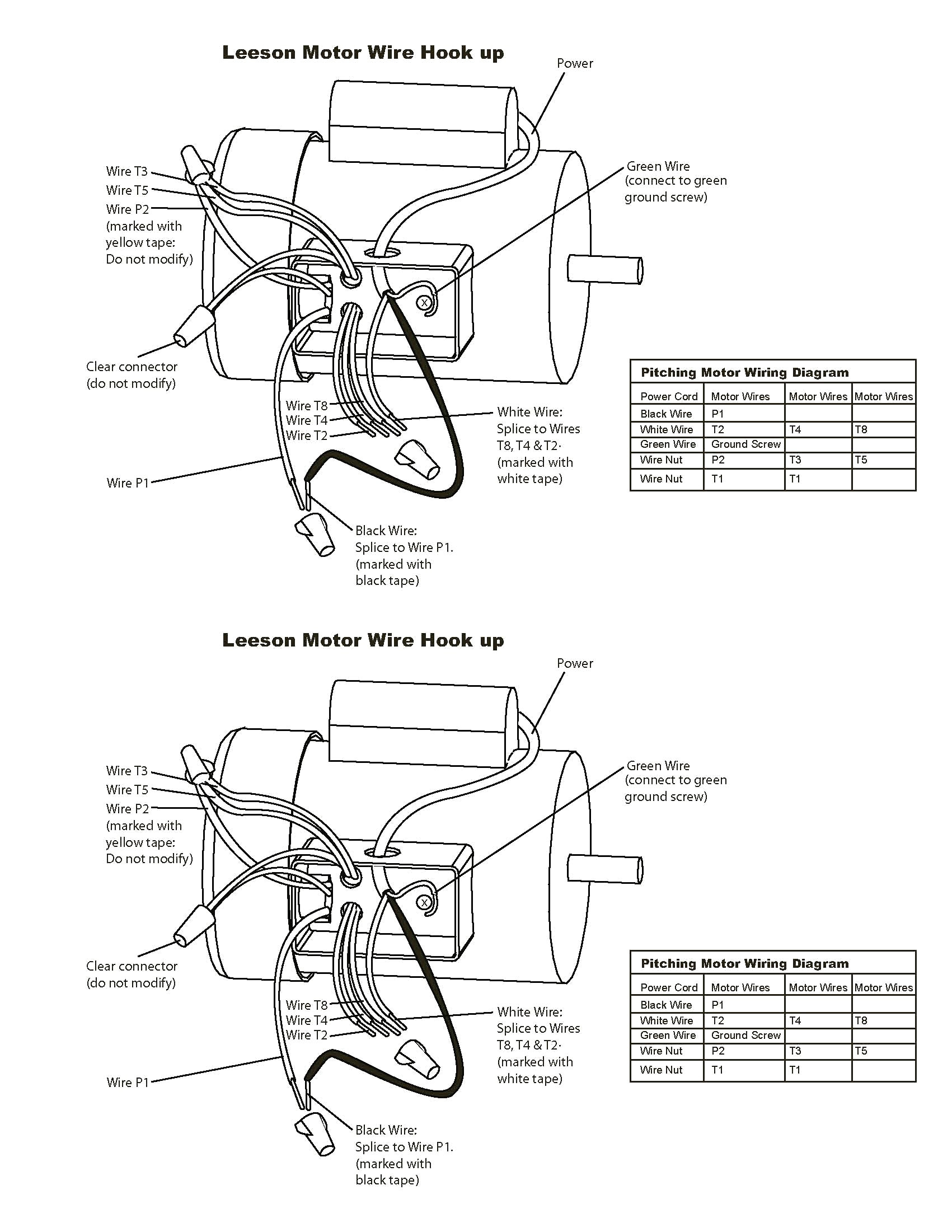 Baldor Motor Wiring Diagrams Single Phase - Coearth
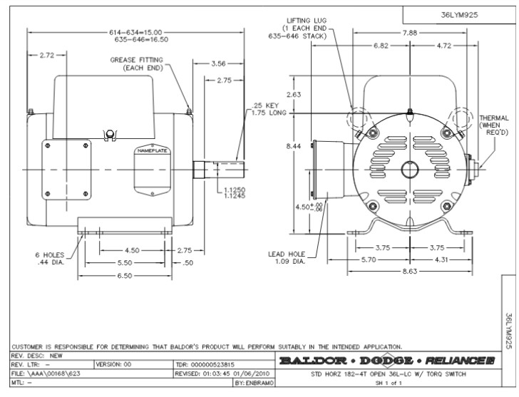 Baldor Motor L1410t Wiring Diagram - Wiring Diagram and Schematic Role
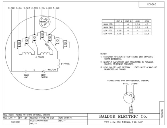 Baldor 15 Hp Single Phase Motor Wiring Diagram - Wiring Diagram
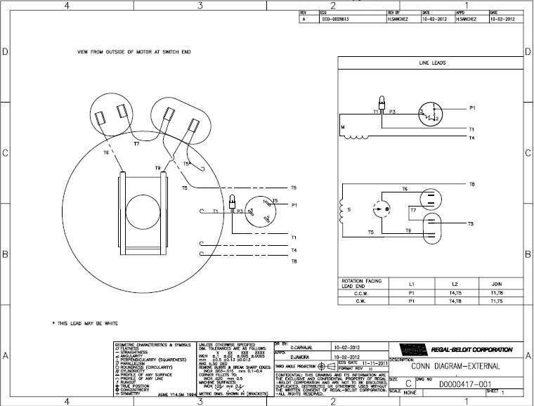 13+ Baldor Motor Wiring Diagrams Single Phase | Robhosking Diagram
