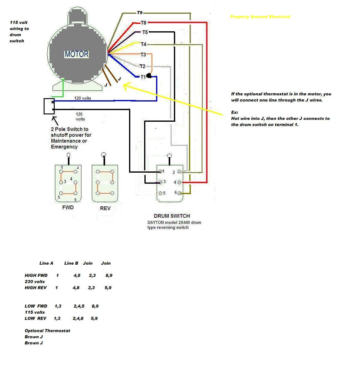
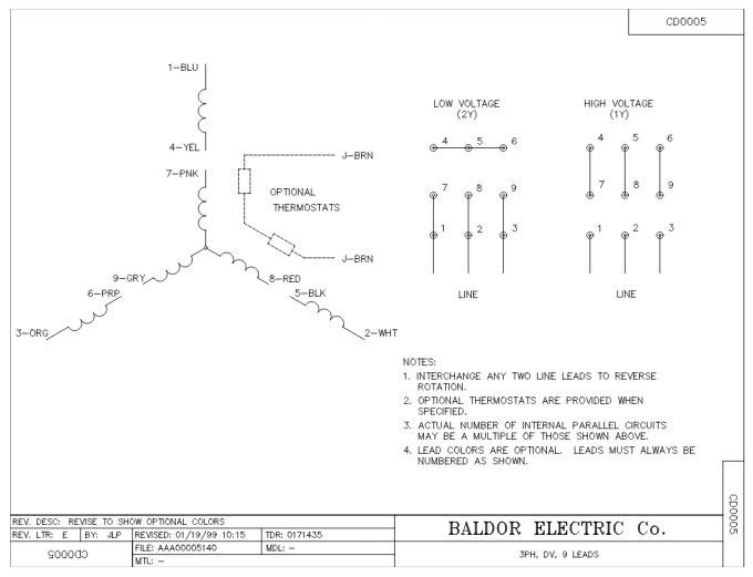
On 12-wire motor wired high voltage (i.e., 480V), 10T, 11T 12T be connected but connected anything else. other 9 wires be connected in 9-wire motor (note a 9-wire motor, equivalent T10, T11 T12 internally connected together). L1 T1, L2 T2, L3 T3, T4 T7, T5 T8 T6 .
 The wiring diagram a Baldor 3 phase motor made of primary sections: power input terminals, control circuits, motor terminals, the overload protector terminal. the diagram, power input terminals, marked L1, L2, L3, those are connected the power source.
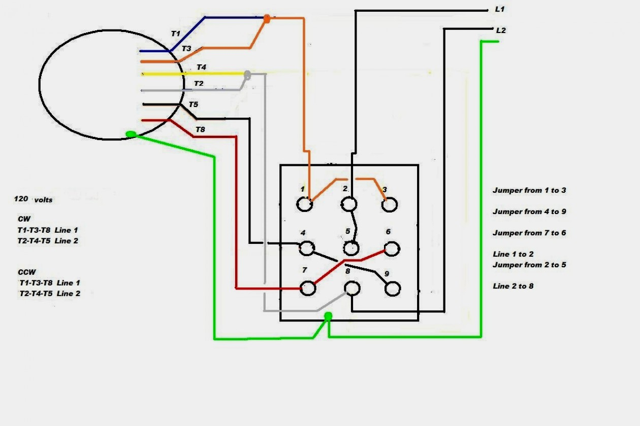
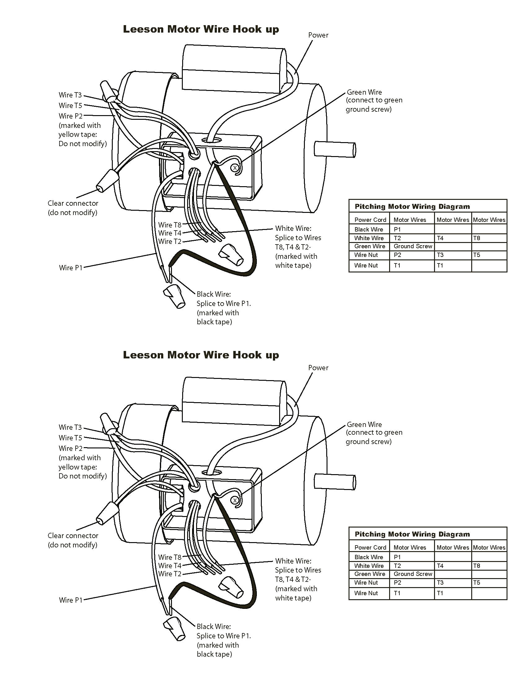
 This motor be installed accordance National Electric Code, NEMA MG-2, IEC standards local codes. WIRING Connect motor shown the connection diagrams. this motor installed part a motor control drive system, connect protect motor to control manufacturers diagrams.
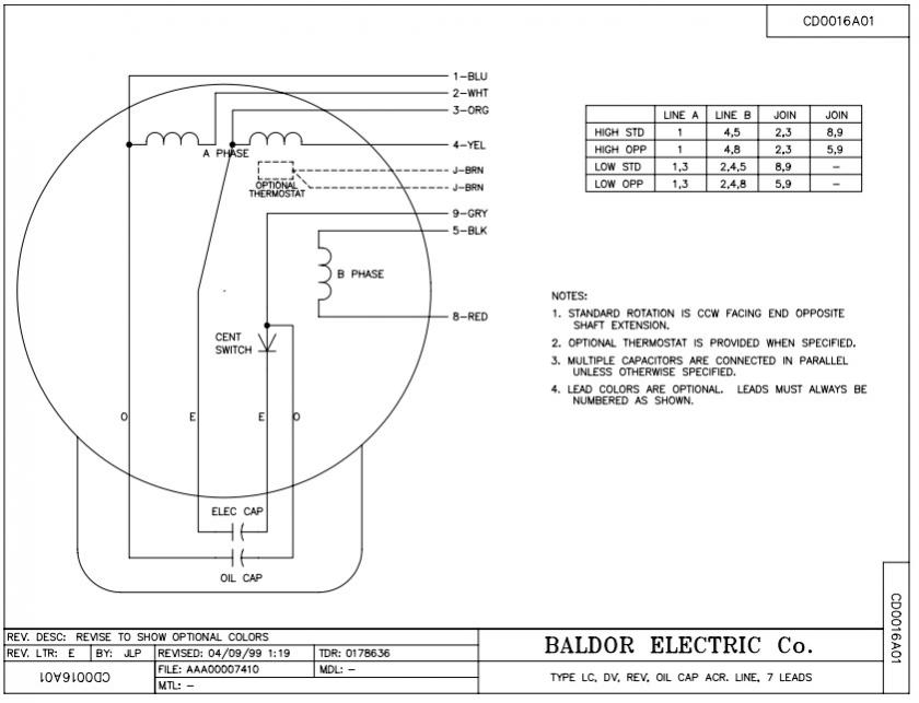 Single-phase motors commonly in residential applications, three-phase motors suitable industrial settings. . Follow wiring diagrams: Baldor electric motors with wiring diagrams provide guidance how properly connect wires. refer the wiring diagram by manufacturer carefully .
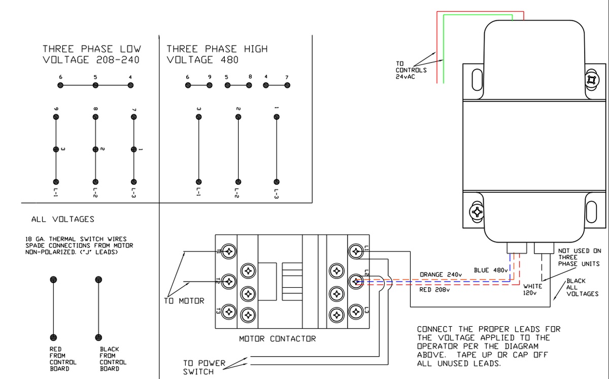 Here a step-by-step guide help wire Baldor 3 phase motor: First, sure have necessary tools equipment, as wire strippers, screwdriver, electrical tape. Next, locate wiring diagram your specific Baldor 3 phase motor model. diagram outline different wires terminals the motor.
 The wiring diagram a Baldor 3 hp motor a visual representation how various components connected. typically includes information the motor's voltage, amperage, speed ratings, well the proper wiring connections the power supply. . as three-phase AC source. voltage frequency the .
 Single-phase Motors: Baldor single-phase motors widely in residential small commercial applications, offering simplicity cost-effectiveness. Three-phase Motors: Baldor three-phase motors highly efficient commonly in industrial settings, providing power output smoother operation. Motor Efficiency
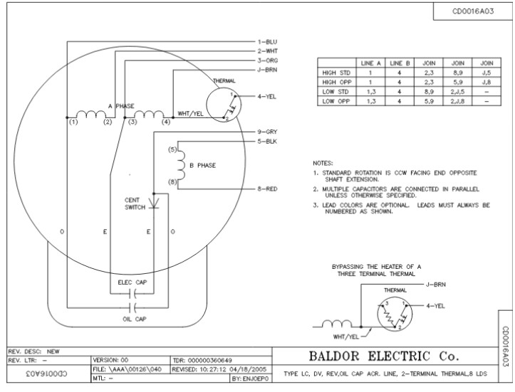 Overall, wiring Baldor 3 phase motor requires careful attention detail adherence the motor's wiring diagram. understanding basics motor wiring following proper procedures, can successfully wire Baldor 3 phase motor ensure optimal performance various industrial commercial applications.

 Here an of Baldor three-phase motor wiring diagram: diagram shows Baldor 10 HP, 208/230/460 V, three-phase motor. motor's nameplate information shown the top the diagram. motor's terminal connections labeled T1, T2, T3. power source's voltage phase shown the bottom the diagram.
 Baldor Generator Wiring Diagrams
 Baldor Three Phase Motor Wiring Diagram - Wiring Diagram
 Baldor Three Phase Motor Wiring Diagram - Wiring Diagram and Schematic
 Baldor 220 3 Phase Wiring Diagram
 Baldor Motor Wiring Diagrams 3 Phase
 Baldor 3 Phase Motor Wiring Diagram
 Baldor Motor Wiring Diagrams 3 Phase - Easy Wiring
 Baldor Electric Motor Wiring Diagrams
 Baldor Electric Motor Wiring Diagrams
 Electric Motor Wiring Diagram 3 Phase
 Baldor Three Phase Motor Wiring Diagram - Wiring Diagram
