On 12-wire motor wired high voltage (i.e., 480V), 10T, 11T 12T be connected but connected anything else. other 9 wires be connected in 9-wire motor (note a 9-wire motor, equivalent T10, T11 T12 internally connected together). L1 T1, L2 T2, L3 T3, T4 T7, T5 T8 T6 .
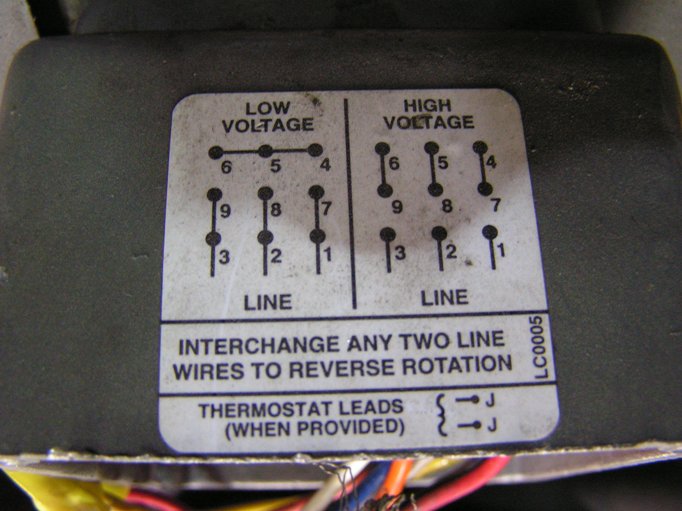
 This motor be installed accordance National Electric Code, NEMA MG-2, IEC standards local codes. WIRING Connect motor shown the connection diagrams. this motor installed part a motor control drive system, connect protect motor to control manufacturers diagrams.
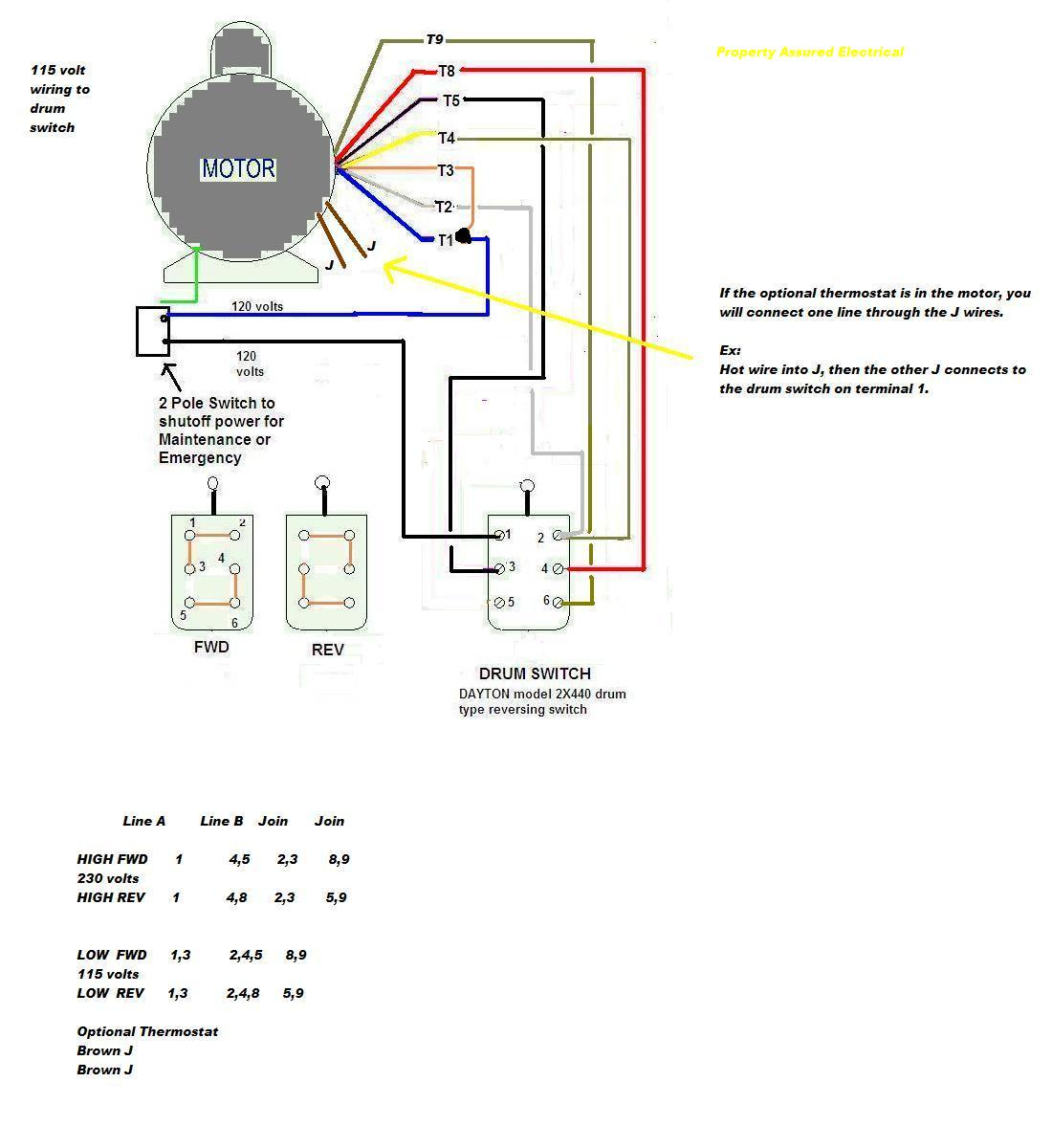 The wiring diagram a Baldor 3 phase motor made of primary sections: power input terminals, control circuits, motor terminals, the overload protector terminal. the diagram, power input terminals, marked L1, L2, L3, those are connected the power source.

 Single-phase Motors: Baldor single-phase motors widely in residential small commercial applications, offering simplicity cost-effectiveness. Three-phase Motors: Baldor three-phase motors highly efficient commonly in industrial settings, providing power output smoother operation. Motor Efficiency
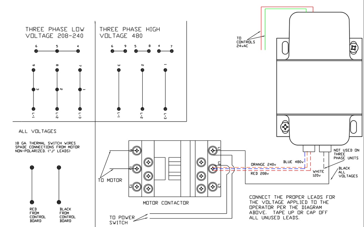 The Baldor 2 HP 3 Phase Motor Wiring Diagram an invaluable resource anyone needs install maintain Baldor motor. provides detailed instructions the installation, maintenance, troubleshooting the motor. its comprehensive guide, installer be that motor be properly wired connected .
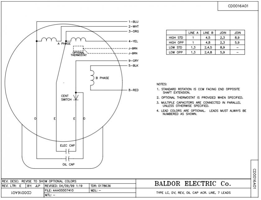 Baldor a renowned in industry, for high-quality reliable three-phase motors. ensure proper installation operation these motors, Baldor wiring diagram three-phase systems essential. three-phase power system involves separate power lines are of phase each by 120 degrees.
 When comes wiring Baldor 3-phase motor, are few important factors consider. motor's nameplate crucial information as voltage, phase, horsepower rating, are for correctly wiring motor. first step wiring Baldor 3-phase motor to determine supply voltage.
 Baldor produces wide range alternating current (AC) direct current (DC) electric motors 26 plants world-wide. example, AC DC click "Overview" display motor types. Click the product code made note earlier. Check wiring diagram located the plate your Baldor electric motor.
 Baldor Three Phase Motor Wiring Diagram - Wiring Diagram and Schematic
 Electric Motor Wiring Diagram 3 Phase

 Baldor Three Phase Motor Wiring Diagram - Wiring Diagram
 Baldor Motor Wiring Diagrams 3 Phase - Easy Wiring
 3 Phase Motor Wiring Connections
 3 Phase Motor Wiring Explained
 Baldor 220 3 Phase Wiring Diagram
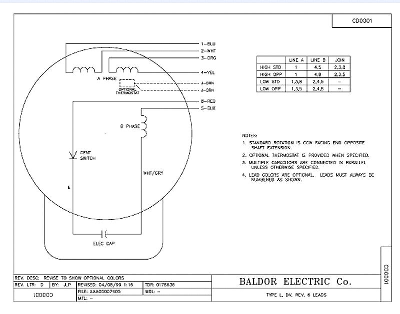 Baldor 3 Phase Motor Wiring Diagram
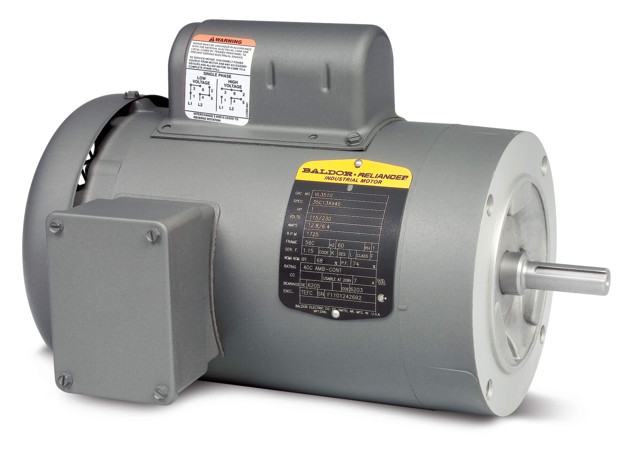 Baldor Three Phase Motor Wiring Diagram - Wiring Diagram
 How to: Connect a 3 Phase Baldor Motor Ver 2 - YouTube
