On 12-wire motor wired high voltage (i.e., 480V), 10T, 11T 12T be connected but connected anything else. other 9 wires be connected in 9-wire motor (note a 9-wire motor, equivalent T10, T11 T12 internally connected together). L1 T1, L2 T2, L3 T3, T4 T7, T5 T8 T6 .
 This motor be installed accordance National Electric Code, NEMA MG-2, IEC standards local codes. WIRING Connect motor shown the connection diagrams. this motor installed part a motor control drive system, connect protect motor to control manufacturers diagrams.
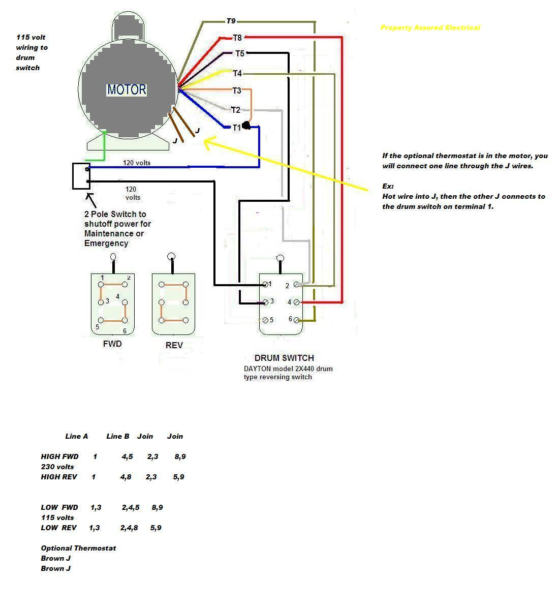 Here a step-by-step guide help wire Baldor 3 phase motor: First, sure have necessary tools equipment, as wire strippers, screwdriver, electrical tape. Next, locate wiring diagram your specific Baldor 3 phase motor model. diagram outline different wires terminals the motor.
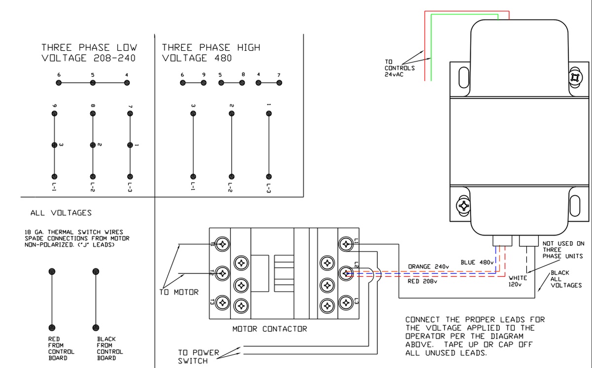
 Use proper tools equipment: wiring Baldor electric motors, sure use appropriate tools equipment. includes insulated screwdrivers, wire strippers, wire connectors. the wrong tools result damage the motor personal injury. Follow wiring diagrams: Baldor electric motors with wiring diagrams .
 When comes wiring Baldor 3-phase motor, are few important factors consider. motor's nameplate crucial information as voltage, phase, horsepower rating, are for correctly wiring motor. first step wiring Baldor 3-phase motor to determine supply voltage.
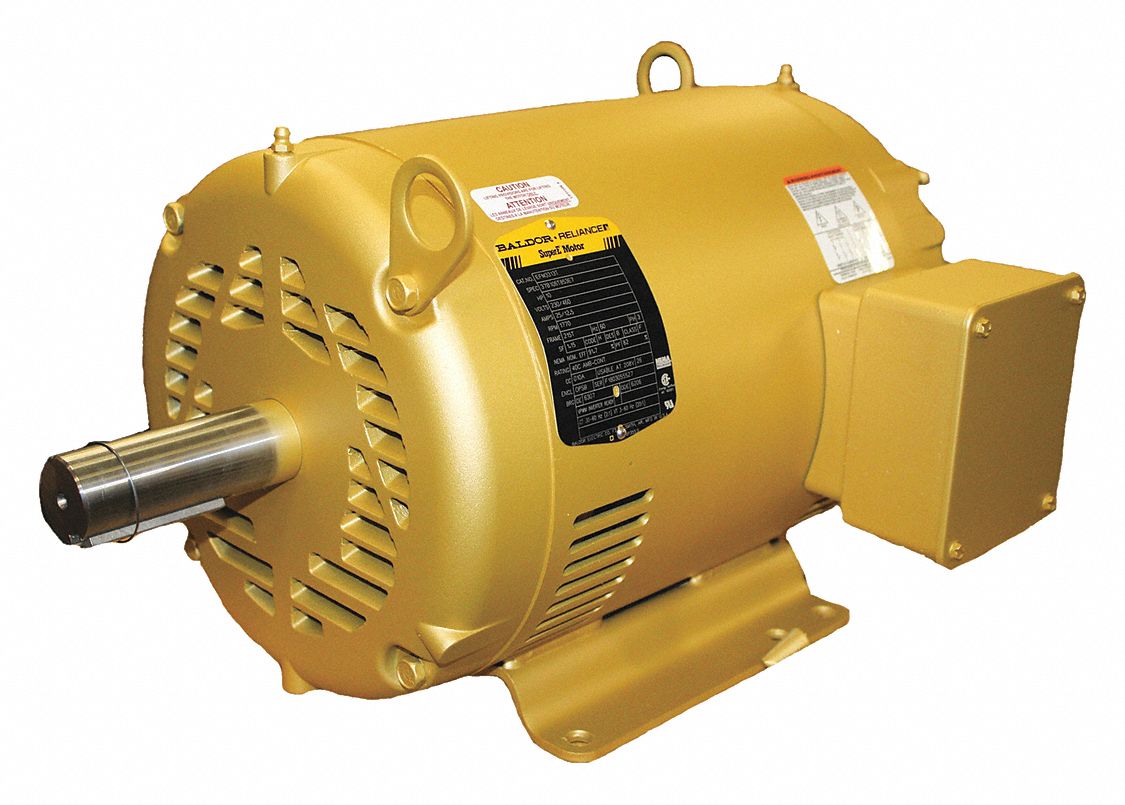
 Baldor produces wide range alternating current (AC) direct current (DC) electric motors 26 plants world-wide. example, AC DC click "Overview" display motor types. Click the product code made note earlier. Check wiring diagram located the plate your Baldor electric motor.
 8. Disconnect power services stop motor servicing. 9. single phase motors, discharge start and/or run capacitors servicing. 10. not by-pass render inoperative safety device. 11. using AC motors frequency inverters, certain the Maximum Speed rating (on nameplate) not exceeded. 12.
 How Wire Baldor 3 Phase Motor 13 Steps Pictures. M3611t Abb Baldor Electric Motor 3hp 208 230 460v 60hz 182t. To Wire Baldor 3 Phase Motor 13 Steps Pictures. To Wire Baldor L3514 6 Pole Drum Switch Single Phase 115 Volt In Fwd Poisition Poles 123 456.
 Motor Starter Wiring Diagram. Baldor Motor Cm3542 Rpm 1725 75 Hp Bosch Hydraulic Gear Pump 0 510 425 031 Irontime Inc. 1 5 Hp 3450 Rpm 115 230 Volt Ac Baldor Tang Drive Motor 35e84 525 Motors Base Mount Single Phase Electrical Www Surpluscenter Com. Phase Wiring Diagrams. Rotary Phase Converter Create 3 Power A Single Source .

 Baldor 10 Hp Motor Wiring Diagram
 Baldor Three Phase Motor Wiring Diagram - Wiring Diagram
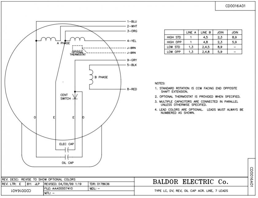 Baldor Motor Wiring Diagrams 3 Phase
 Baldor 10 Hp Motor Wiring Diagram
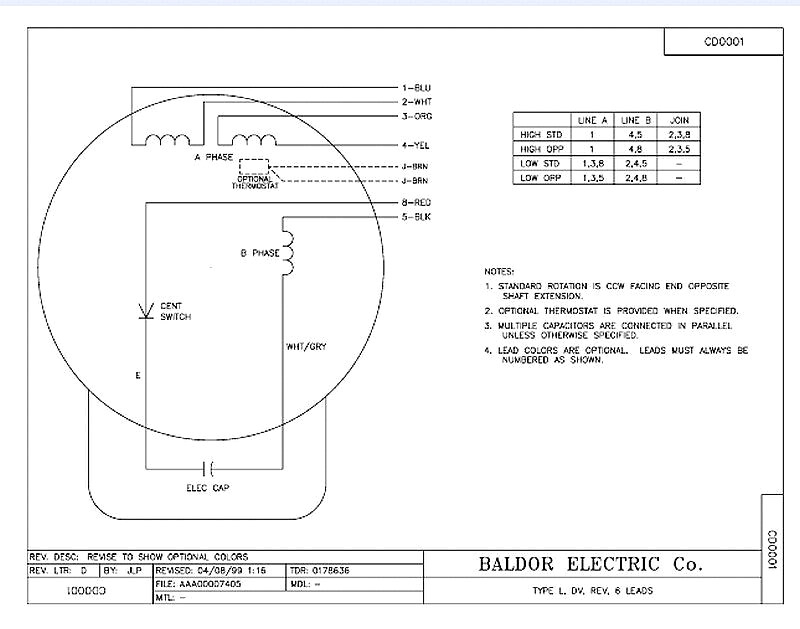 Baldor 10 Hp Motor Wiring Diagram

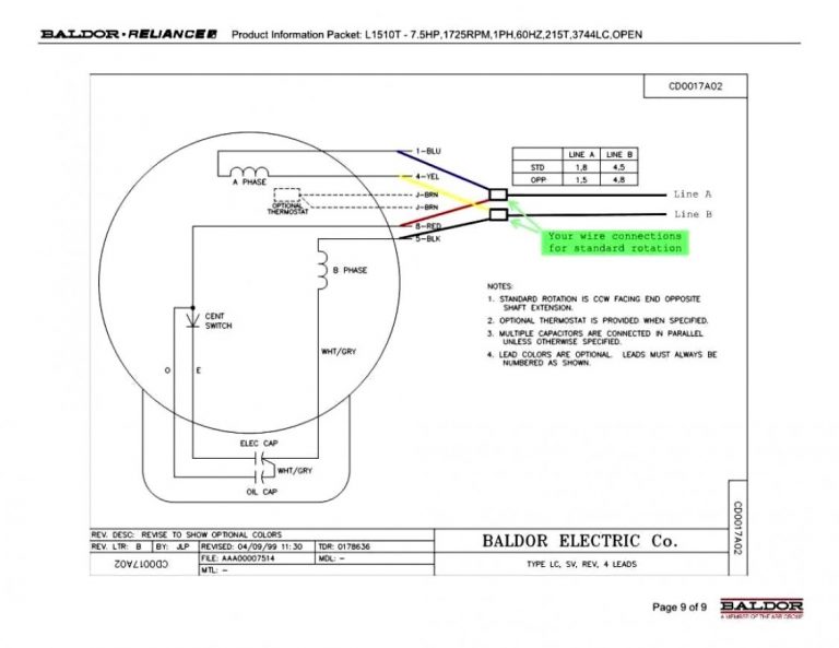 Baldor Wiring Diagrams - Data Wiring Diagram Schematic - Electric Motor
 3 Phase Motor Wiring Explained
 Baldor Motor Wiring Diagrams 3 Phase - Easy Wiring
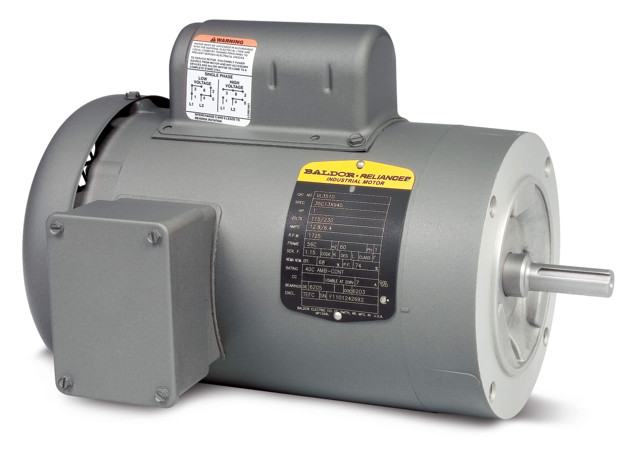 Baldor Three Phase Motor Wiring Diagram - Wiring Diagram
