Harley headset 7 pin DIN pinout information. . at 7-pin connector the index groove the connector the twelve o'clock position, bottom pin #2. clockwise the index groove pins #6, #1, #4, #2, #5, #3, #7. . headset wiring diagram that wiring diagram correct. you finish you wanted do .
 I can't find colour wiring diagram pin a 7 din plug Beogram 2000. ill looking. anyone ever replaced 7 din plug I'd so grateful you let know colour wire sequence. you. 14 March 2024 12:21 #53417. Stoobie. GOLD Member.
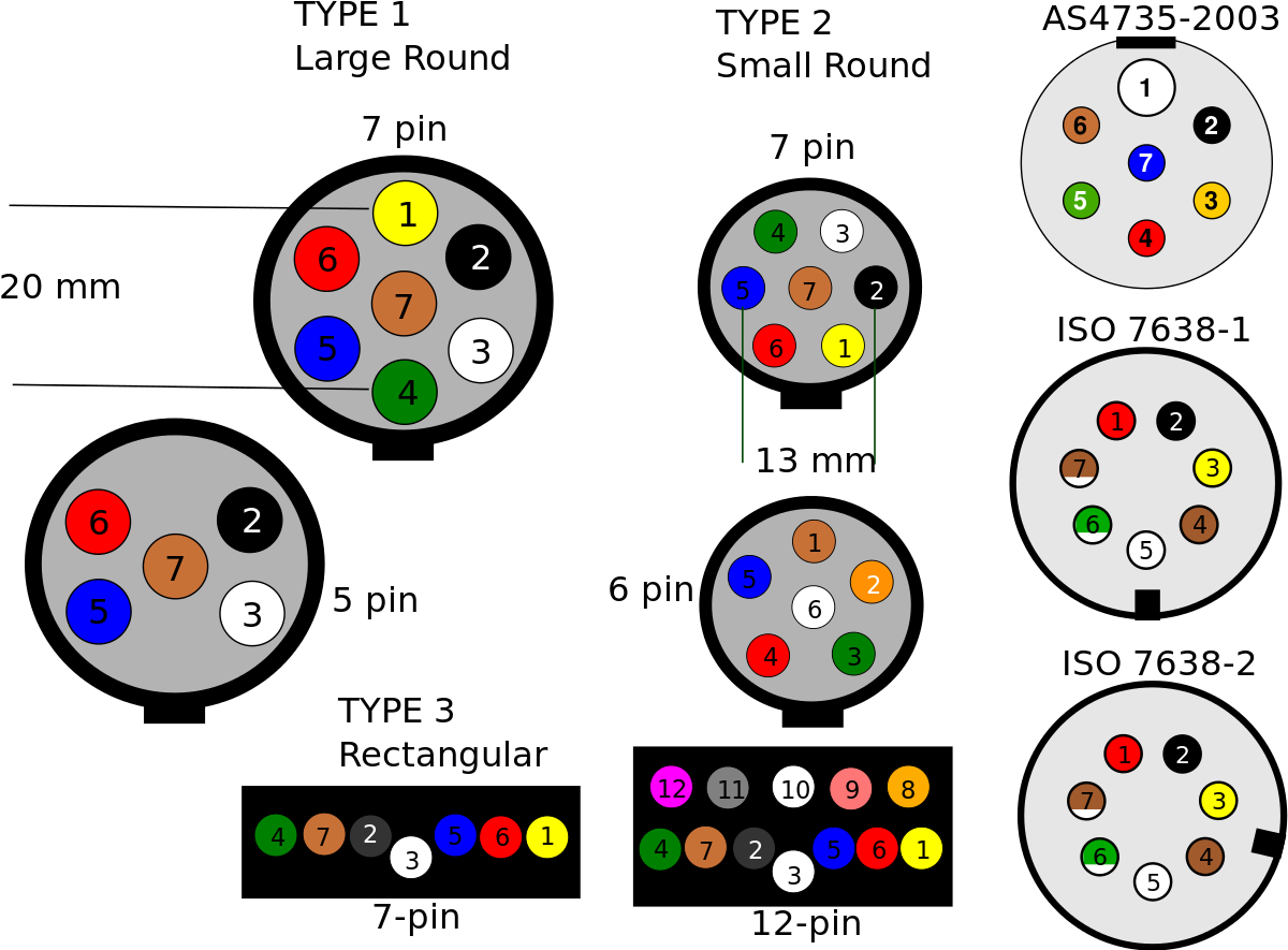 Step 2: Familiarize with wiring diagram. beginning actual wiring process, carefully study wiring diagram with 7 pin connector. diagram show which color wires correspond each function. Step 3: Prepare wires. Cut strip wires the vehicle's wiring harness, the wire .
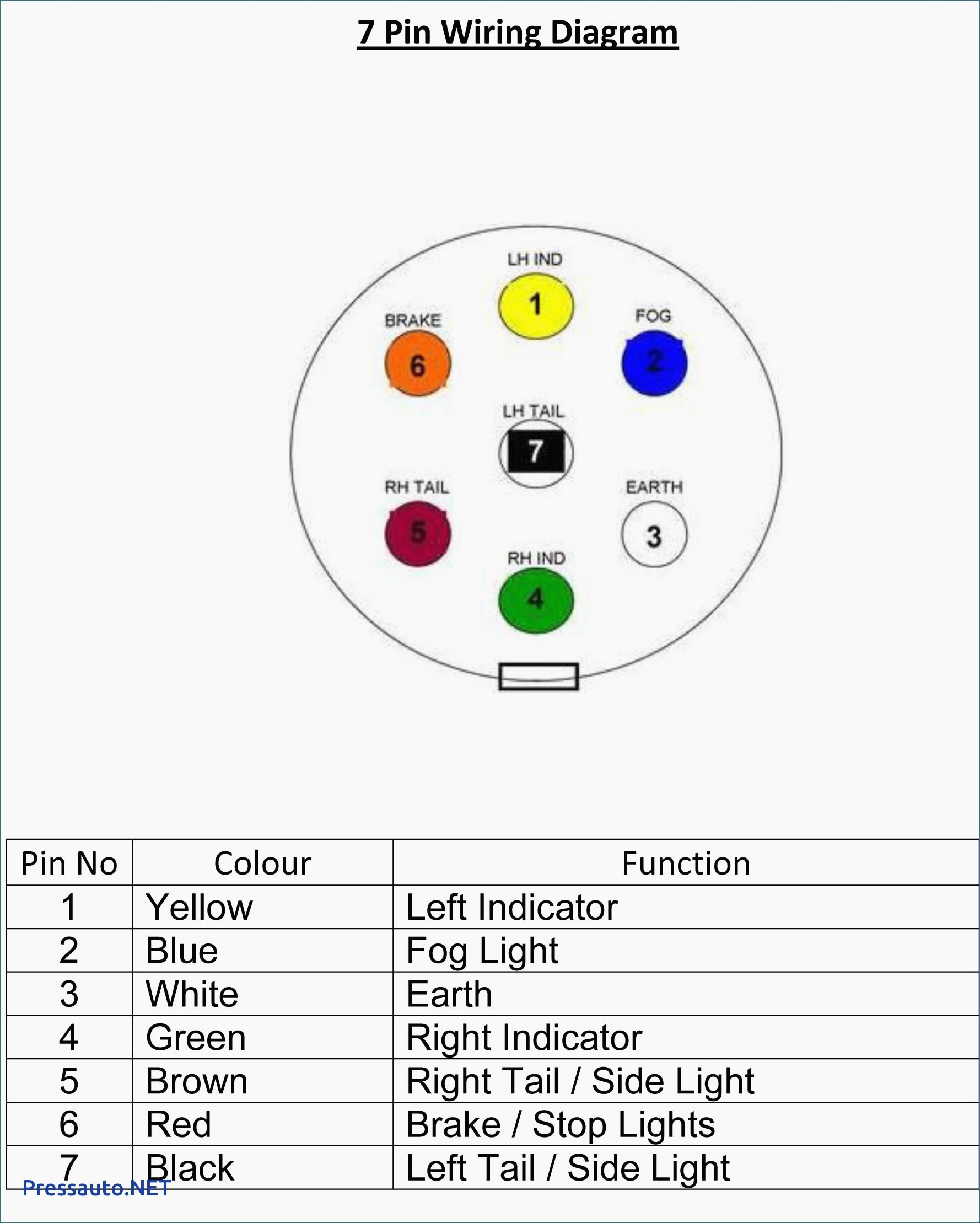
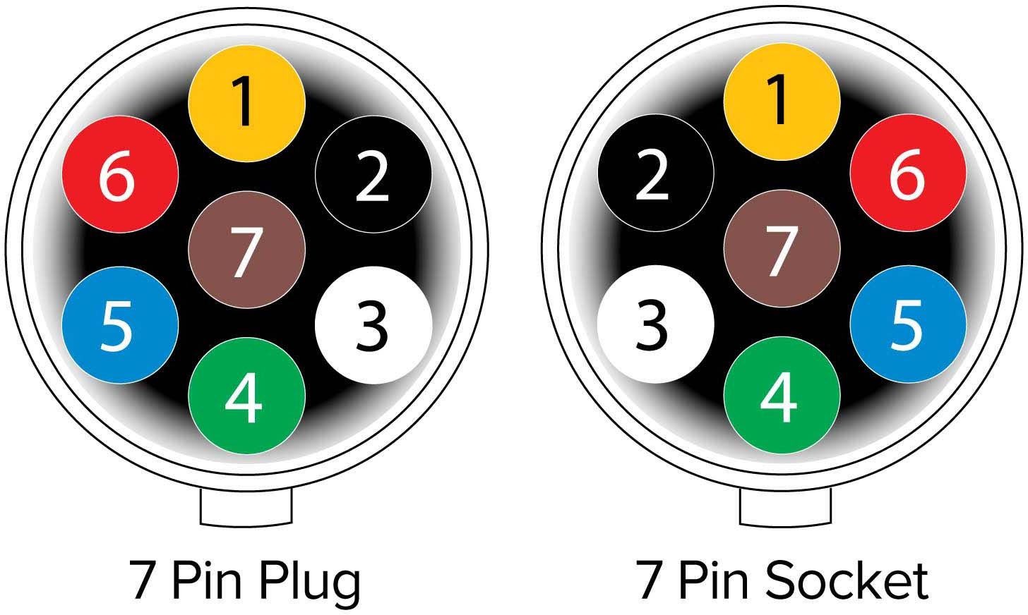 A wiring diagram a 7-pin plug a detailed illustration showing electrical connections circuitry a 7-pin plug, is commonly for trailers towing vehicles. diagram a clear visual representation how connect different wires pins the plug, ensuring proper functionality safety. is valuable resource individuals need .
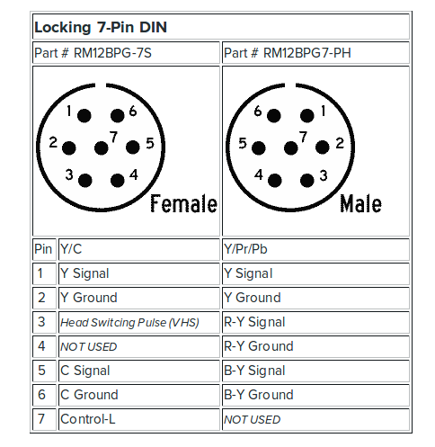 You the Beogram output DIN pins 3 5 go RCA Left Right respectively. Pin 2 ground. if are making own lead only a 5 pin DIN socket will to removed DIN pins 6 7 (they unscrew). EDIT: Pin numbers into 7-pin DIN socket (or at solder side DIN plug):
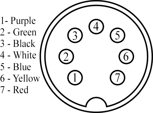 7 pin din plug wiring diagram. Thread starter allanarmy; Start date Sep 24, 2012; Tags Speakers Sidebar Sidebar. Home. Forums. Electronics & Wearables. Audio . A. allanarmy Honorable. Sep 23, 2012 1 0 10,510. Sep 24, 2012 #1 Hello, was wondering you tell the correct wiring diagram 7 pin din pulg i set speakers my .
 2-Pin DIN Speaker Connections. 2-pin DIN not round connector the common 3 7-pin varieties. the body typically round, is shroud, it simply one wide spade-type terminal one terminal. round pin wired the positive side the amplifier output; spade terminal the negative:
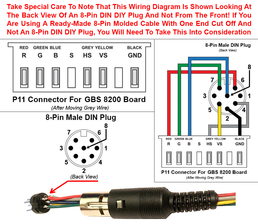
 The Basics the Din Connector: Pin Configuration Key Features. the world electronic devices, Din connector plays crucial role facilitating transfer data power various components. . Understanding proper wiring diagrams following practices essential successful connections optimal .
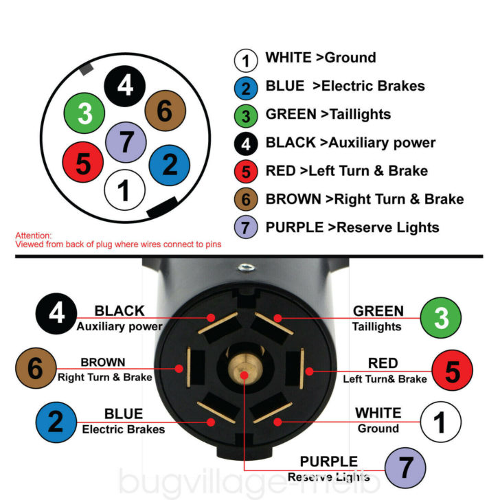 Common Applications 7 Pin Wiring Diagrams. 7-point connection system widely in practical applications multiple electrical functions to managed simultaneously. is common vehicles, trailers, various towing setups, different components to linked tasks as lighting .
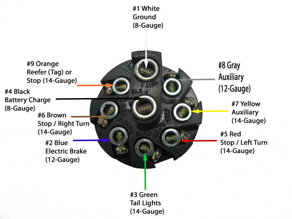 Here two wiring diagrams the 7 pin 'N' type trailer electrical plug. first diagram a simple set of brake lights, indicators two side lights. Click the image to enlarge it. second diagram shows brake lights, indicators, side lights a fog light. Click the image to enlarge it.
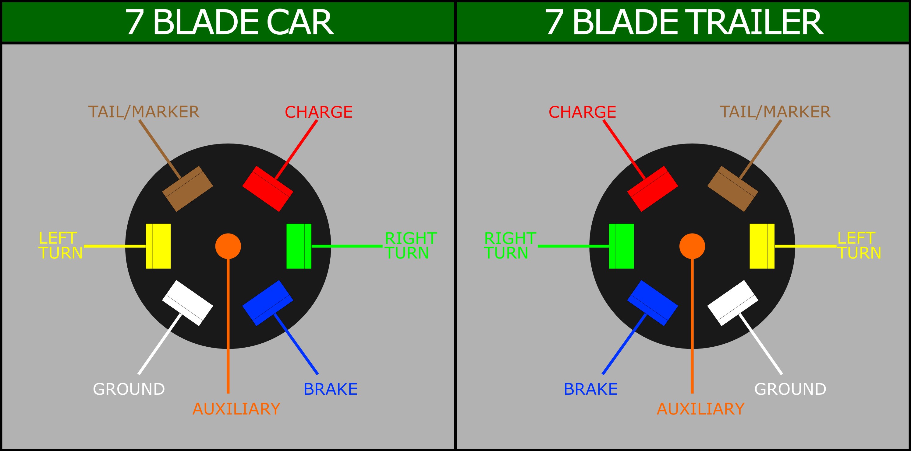 7 pin caravan plug wiring diagram - IOT Wiring Diagram
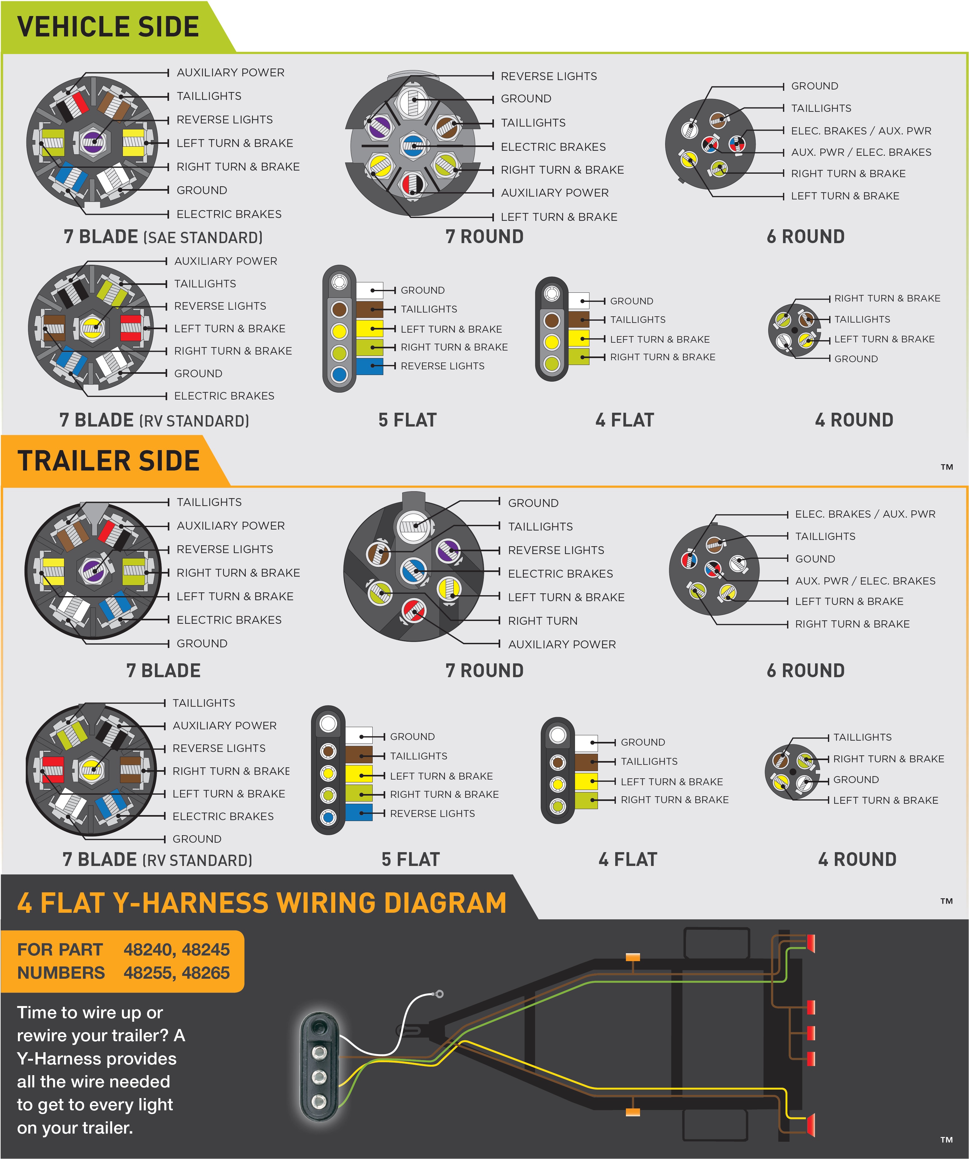 7 Pin Trailer Plug Wiring Diagram - Database - Faceitsaloncom

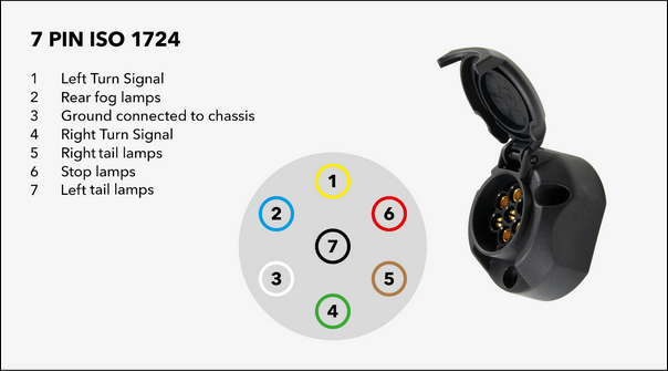 7-pin wiring diagram | Trailer 12N | ECS Electronics
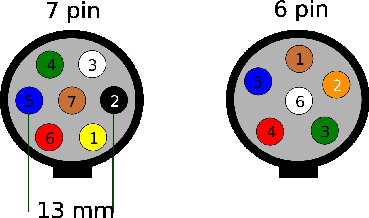 Seven Pin Flat Trailer Wiring Diagram
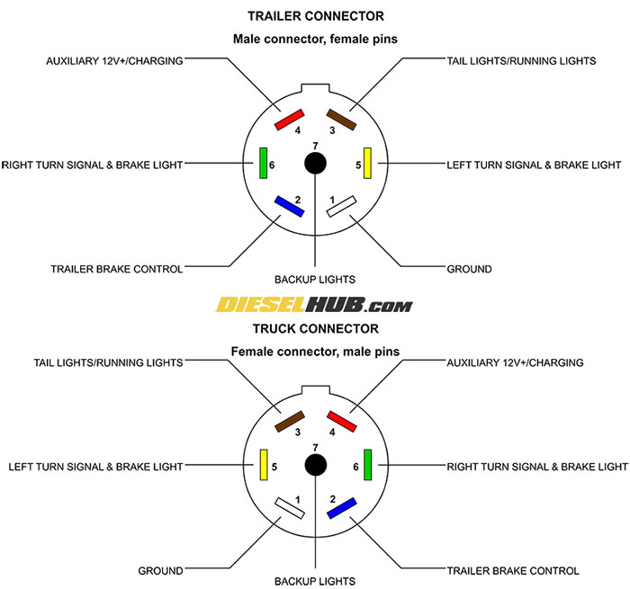 Trailer Connector Pinout Diagrams - 4, 6, & 7 Pin Connectors
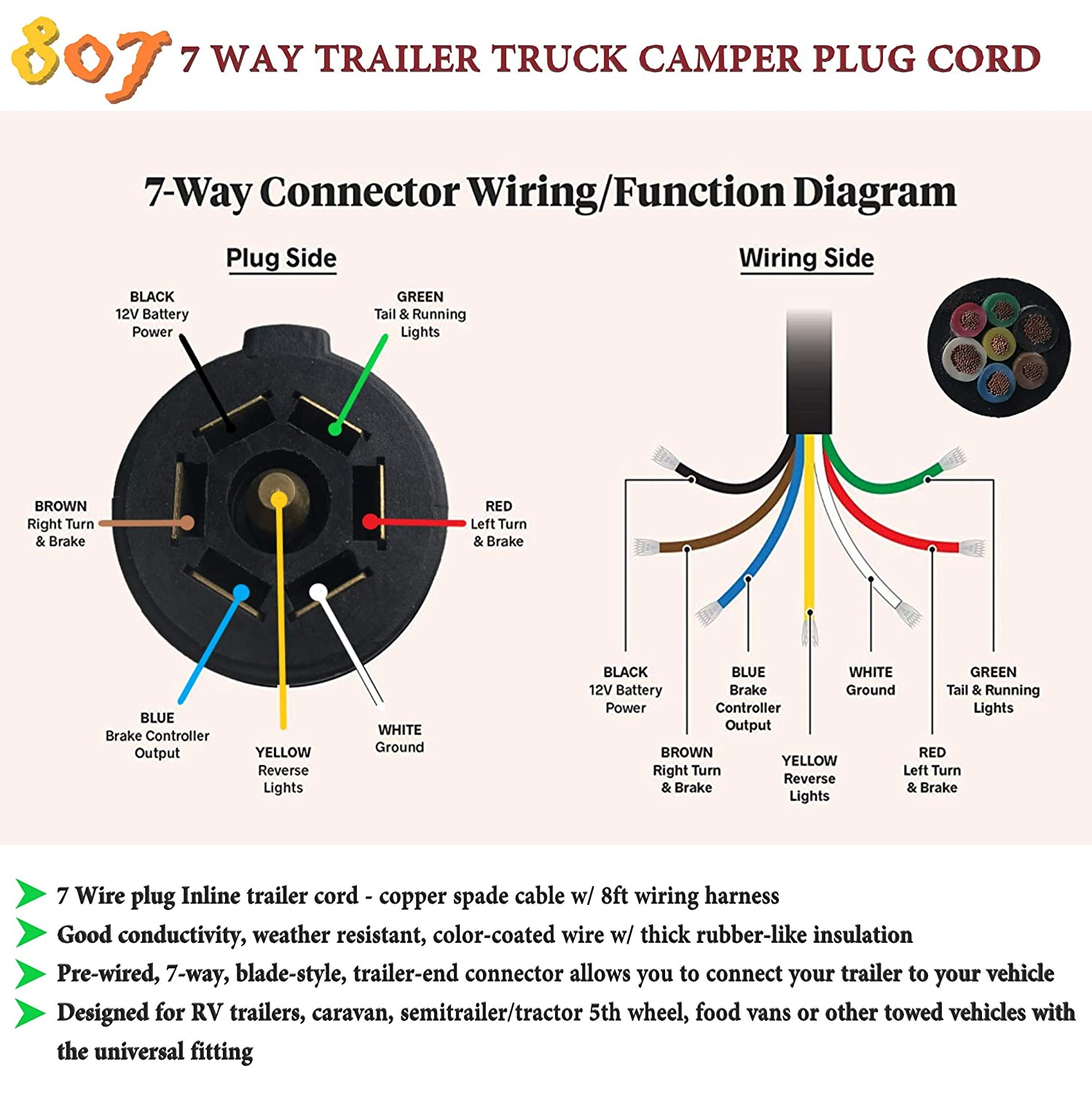 7 Pin Wiring Diagram Auto
 How To Wire A 7 Pin Trailer Plug With 4 Wires
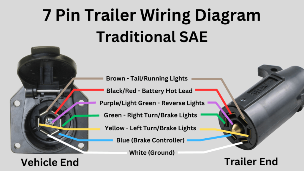 How To Connect Your 7 Pin Trailer Wiring Easily (Diagram Included
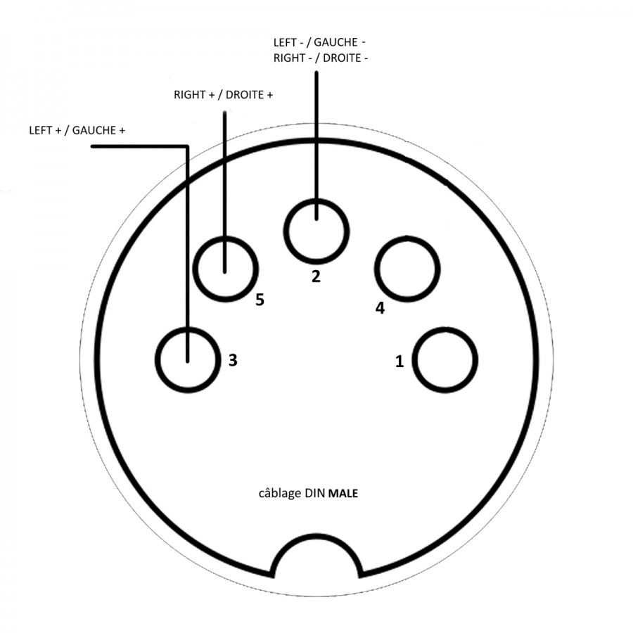 Din Wiring Diagrams
![[DIAGRAM] 7 Pin To 4 Pin Plug Adapter Wiring Diagram - MYDIAGRAMONLINE [DIAGRAM] 7 Pin To 4 Pin Plug Adapter Wiring Diagram - MYDIAGRAMONLINE](http://support.vms4x4.com/help/discussions/problems/10351/assets/89c454636f74b8bd01d62c4693312cf788b50b7b/Dual_Camera_Kit_Pin_Outs.jpg) [DIAGRAM] 7 Pin To 4 Pin Plug Adapter Wiring Diagram - MYDIAGRAMONLINE
[DIAGRAM] 7 Pin To 4 Pin Plug Adapter Wiring Diagram - MYDIAGRAMONLINE
