Wiring 6 wire single phase motor seem a daunting task, with right guide a bit knowledge, can a straightforward process. you're experienced electrician a beginner DIYer, understanding wiring diagram a 6 wire single phase motor essential ensure proper installation functionality.
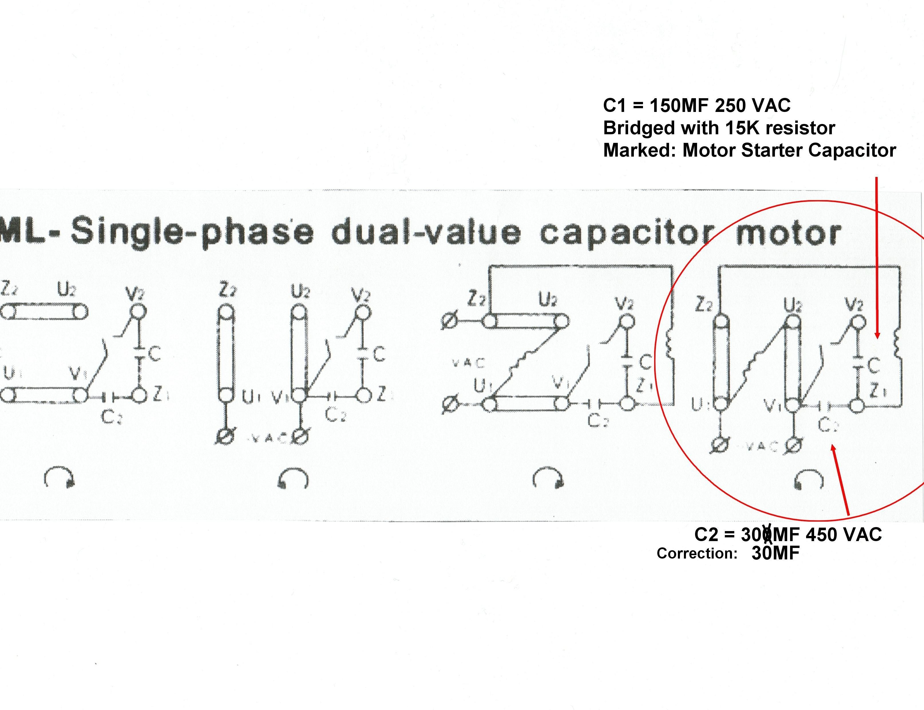 Permanent Split Phase Capacitor Motor Wiring Diagram. as name implies, single phase motor diagram work a split phase generated a capacitor. capacitance the capacitor the reactance the winding shift phase some extent. is permanent capacitor single phase motor wiring diagram.
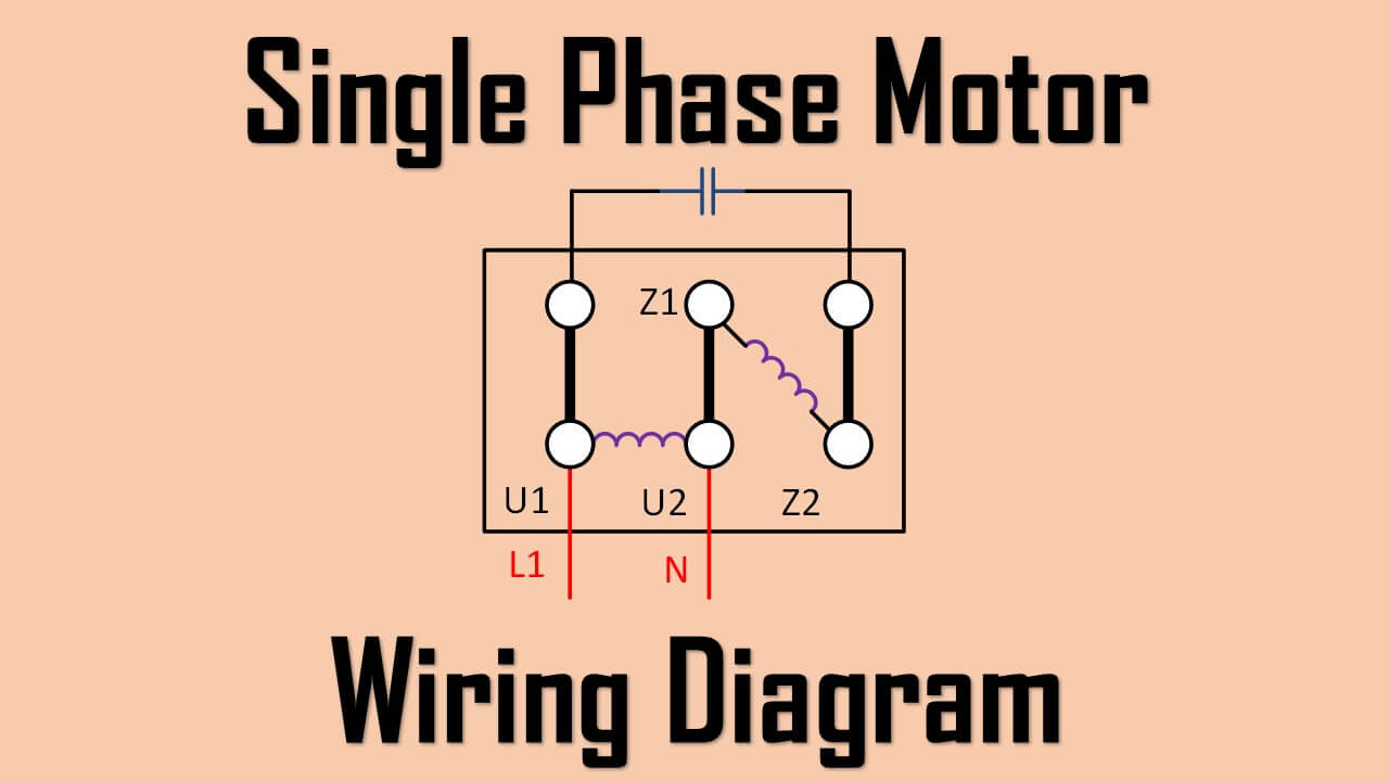 Learn to wire 6-wire electric motor the of detailed diagram. guide walk through step-by-step process provide with the information successfully connect motor. you're replacing old motor installing new one, understanding wiring diagram essential. started today ensure motor wired correctly .
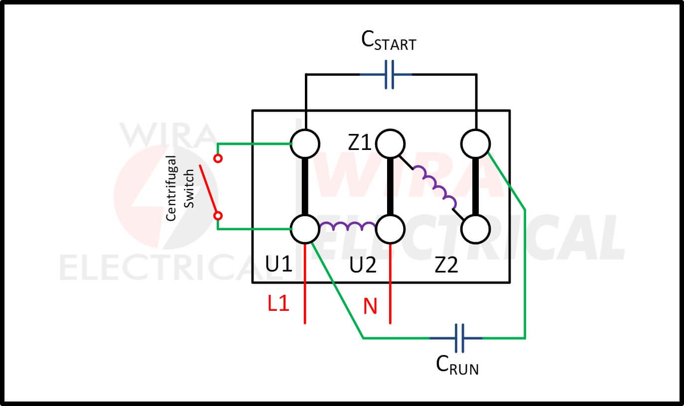 240V wiring L1/hot connect 1, wire nut 2,3,5 together, L2/neutral 4,8. Test motor. will start little slow come to speed a seconds. Put ampmeter the lead to starting cap. the motor up speed amps drop near zero. it doesn't don't your leads marked correctly.
 Single Phase Motors. Variable Speed Motors. Vertical Motors. World Motor Horizontal Motors. Catalogs & Literature. . Wiring Diagrams Available: Accessory Connection. Connection Diagram: Description: 3226: . Single Phase, Dual Voltage, 6 Lead CW Rotation: 915402 : Speed, Winding, Single Voltage, PWS Both Windings Full .
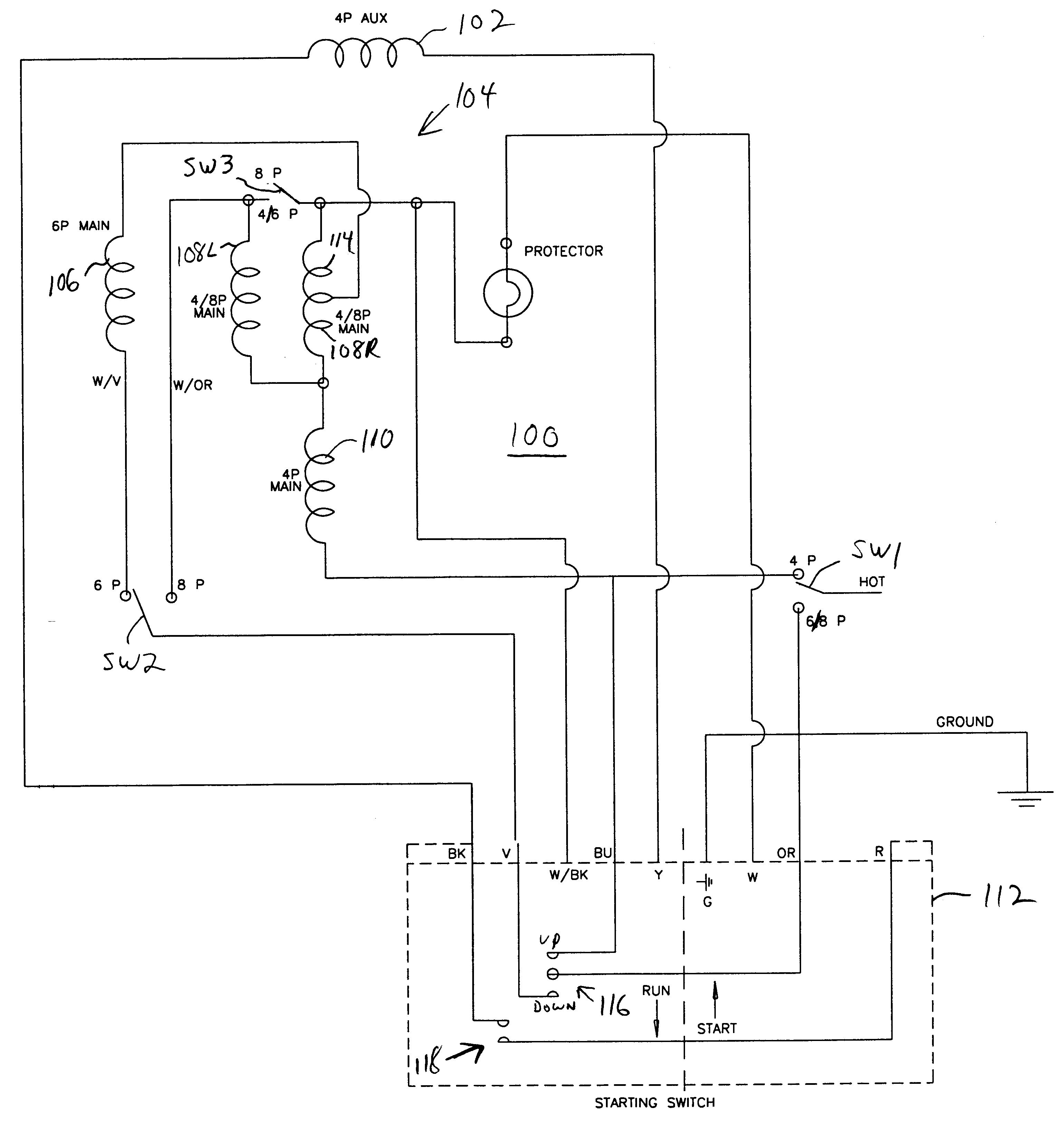 Motor Wiring Diagram 6 Lead, Single Phase, Dual Voltage Connected CW Rotation Facing Shaft End. reverse direction rotation, interchange leads 5 & 8. lead have or cables comprising lead. such case, cable be marked the lead number. Connection Plate: N/A Connection Decal: 912577
 For other SINGLE-PHASE wiring diagrams refer the manufacturers data the motor. Diagram DD6 Diagram DD8 1~ LN Diagram DD9 1~ LN White Brown Blue L1 L2 S/C . Single-phase motors Diag. ER 6 OEDM. EDM Series A-4/5 Diags. ER 6, 7 OFSU146 Diag. ER 11 A-32 OGRE. Sigma Series E-2 Diag. ER 4 OHB. Header Box A-33 Diag. ER 4
 Wiring diagrams single phase motors provide visual representations the electrical connections components involved operating single phase motor. diagrams essential understanding wiring configurations troubleshooting issues may arise. typical wiring diagram a single phase motor includes .
 Typical single phase motor wiring diagrams including HI/Lo voltage, start run capacitors (if used), start run windings centrifugal switches. Single phase motors generally a starter circuit get turning. starter circuit turned by centrifugal switch the motor reaches minimum RPM.
 Step-by-Step Guide Wiring Single Phase Motor. Wiring single phase motor seem daunting, with right information tools, can a straightforward process. a step-by-step guide help ensure successful installation. is breakdown the process: 1. Gather necessary tools equipment
 Electric Motor Wiring Diagram For Appliances
 Vfd Wiring Diagram Single Phase Phase Motor Vfd Single Wirin
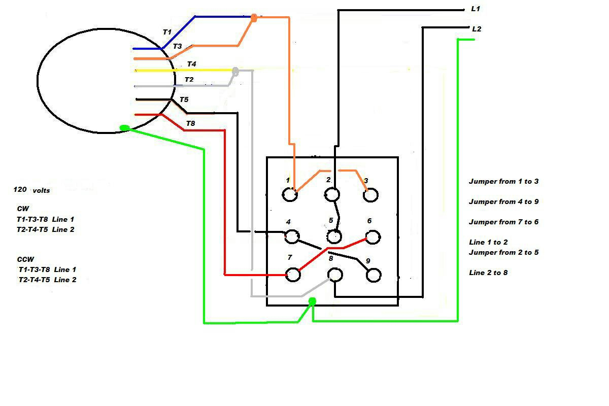 Electric Motor Wiring Diagram Single Phase
![[DIAGRAM] Baldor Single Phase Motor Wiring Diagrams - MYDIAGRAMONLINE [DIAGRAM] Baldor Single Phase Motor Wiring Diagrams - MYDIAGRAMONLINE](https://www.iforgeiron.com/uploads/monthly_2017_05/591727d11b714_motorwiring.jpg.c49fb6750aa2ea7779c731f858034e9d.jpg) [DIAGRAM] Baldor Single Phase Motor Wiring Diagrams - MYDIAGRAMONLINE
[DIAGRAM] Baldor Single Phase Motor Wiring Diagrams - MYDIAGRAMONLINE
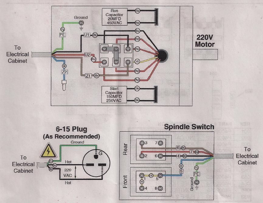 Single Phase Motor Wiring Diagram Pdf 115v Magnetek Wiring2 3 Phase
 Electric Motor 240v Single Phase
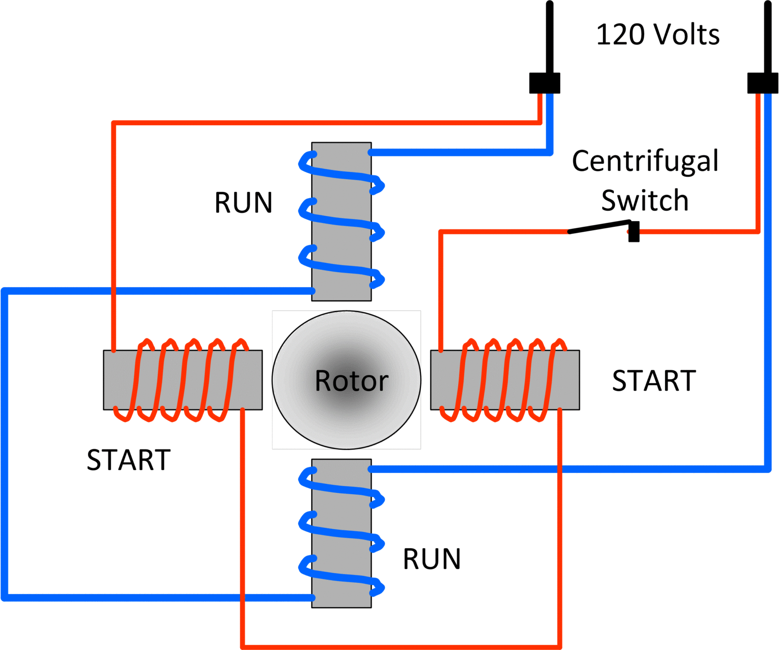 Types of Single Phase Induction Motors | Single Phase Induction Motor
 How To Wire A 6 Wire Motor
 Single Phase Motors Wiring Diagrams
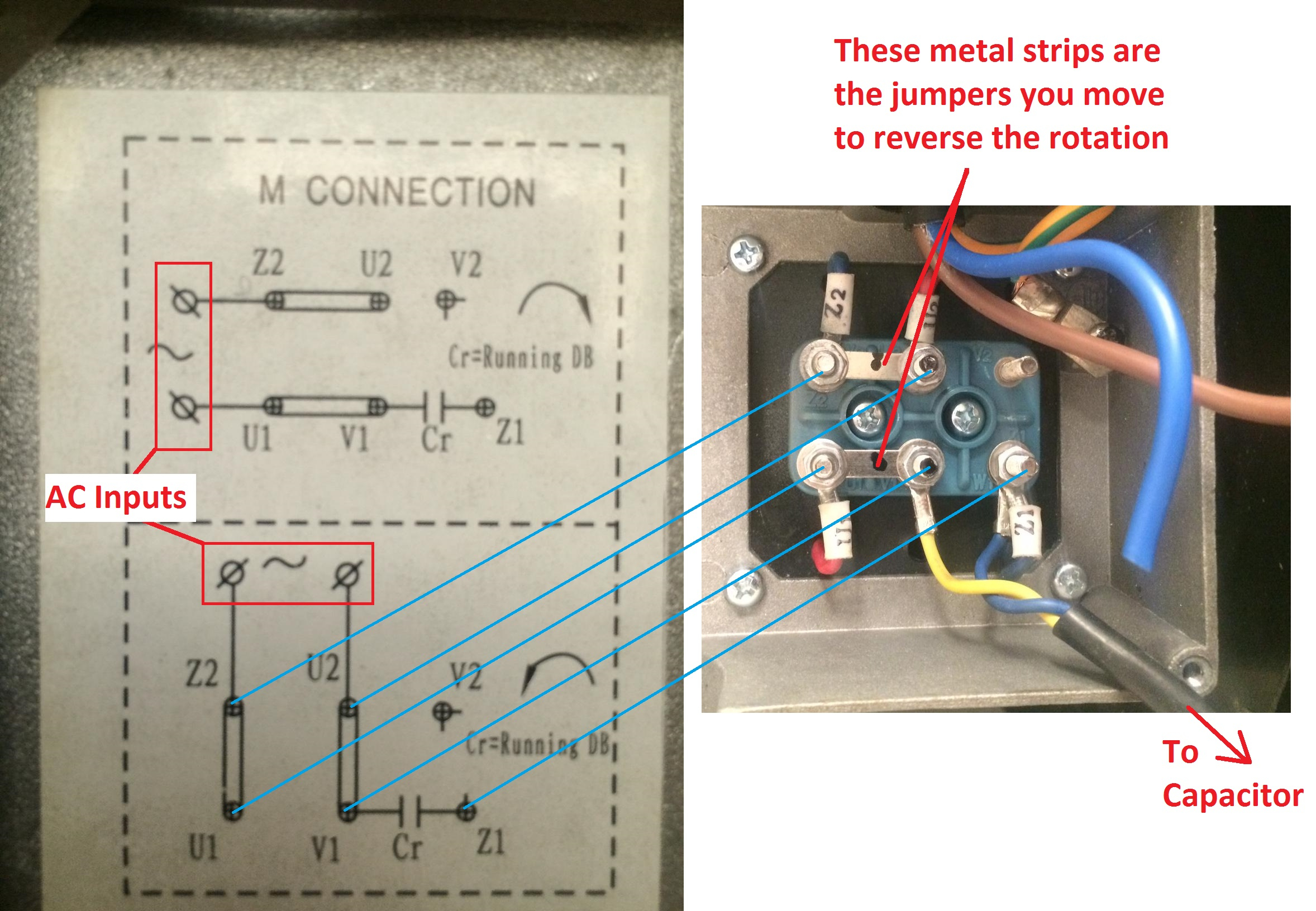 Wiring A Single Phase Motor
