Q-RELAY-3P-INT WIRING DIAGRAM PROGRAM 1 2 PHASE OPERATION 3-phase Q-Relay also support 2-phase single-phase applications. program number phases: ) Press hold test button. phase voltage indicators (V1, V2, V3), turn red the relay click. approx. 6 seconds phase voltage LEDs start
 V V ar in phase, ther efore function operates expected. the external fault, operation not occur IZ and are 180¡ of phase. Observe for balance point fault, V exactly equal IZ. is true the three-phase fault shown (also a phase-to-phase fault) for phase distance function .
 Wiring Diagrams ww introduction . Relays H-q+- (P4Of.t Shown) Closing Opening Rising Press. Press. T T . (For 2 Phase, 3 Wire, L2 T2 common) Sgl. Phase Lines Sizes 0,l 1P Single Phase Sizes 1 Direct Current 6 Pilot Light Red .
 Note due the wrong connection, above diagram an update. the diagram, have shown complete method wiring connection phase failure relay diagram circuit breaker, cont actor, overload relay, push-button switches, electric motor, however, let's talk this step step.
 4. Connect three-phase line-line voltage terminals 3, 4 5 (see Wiring Diagram the side the relay on Page 3 this sheet). connection the neutral ground not required Wye systems. NOT connect output wires terminals 1, 2 8 later (Step 13). 5.
 5. Connect three-phase line-line voltage terminals 1, 2 3 (see Wiring Diagram the side the relay on back this sheet). connection the neutral ground not required Wye systems. NOT connect output wires terminals 7-12 later (Step 12). 6.
 4. Connect three-phase line-line voltage terminals 1, 2 3 (see Wiring Diagram the side the relay Figure 2 reverse side). connection the neutral ground not required Wye systems. NOT connect output wires terminals 7-12 later (Step 12). 5. RESET: standard, D65VMLS Series relays in .
 • Monitor voltage asymmetry, phase sequence, phase loss three-phase 3-wire 4-wire power supplies just Unit. Switch setting 3-phase 3-wire 3-phase 4-wire power supply. • SPDT output relay, 5 at 250 VAC (resistive load). • World-wide power specifications supported one Unit (switchable).
 3-phase 3-wire mode 380, 400, 415, 480 VAC K8AK-PM2 3-phase 4-wire mode 220, 230, 240, 277 VAC . Relationship Mounting Distance K8AK-PM Relays Ambient Temperature (Reference Values) following diagram shows relationship the mounting distances the
 THREE PHASE WIRING DIAGRAM Models SL585UL SL595UL J14 TRANSFORMER J11 J12 LINE J1 L1 J2 L2 J3 L3 J7 COMM WHITE . 12 3 Red light wired AUX RELAY 1. Green light wired AUX RELAY 2. AUX RELAY 1 SWITCHES Red light OFF* OFF . Run-distance be re-learned setting handing again. 53
 Mastering the Basics: A Comprehensive Guide to Understanding 3 Phase

 3 phase failure relay wiring diagram Phase failure relay 3-phase
![[DIAGRAM] 3 Phase Panel Board Wiring Diagram Pdf - MYDIAGRAMONLINE [DIAGRAM] 3 Phase Panel Board Wiring Diagram Pdf - MYDIAGRAMONLINE](https://www.electricaltechnology.org/wp-content/uploads/2013/12/Three-Phase-Electrical-Wiring-Installation-Diagram-According-to-IEC-Color-Code.png) [DIAGRAM] 3 Phase Panel Board Wiring Diagram Pdf - MYDIAGRAMONLINE
[DIAGRAM] 3 Phase Panel Board Wiring Diagram Pdf - MYDIAGRAMONLINE
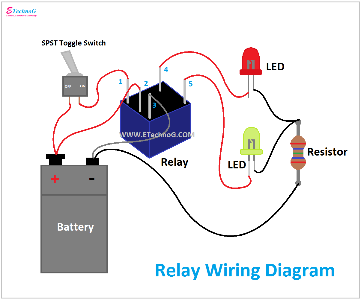 Relay Wiring Diagram and Function Explained - ETechnoG

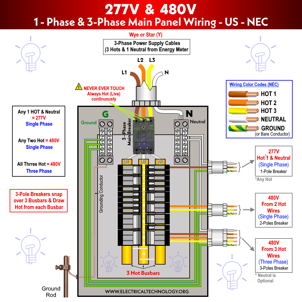
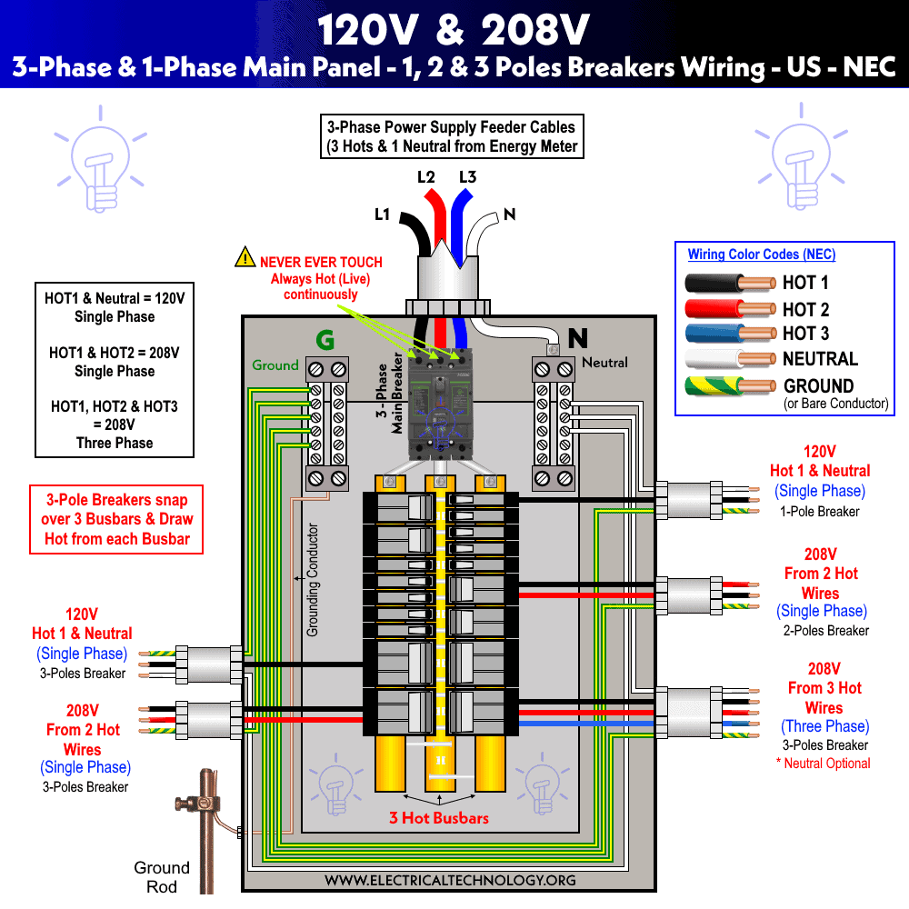
 Understanding 208v 3 Phase Wiring: A Comprehensive Diagram Guide
 Electrical 3 Phase Wiring Diagrams - Circuit Diagram
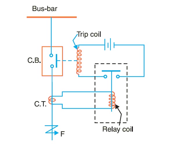 How Protective Relays Work? | StudyElectrical | Online Electrical
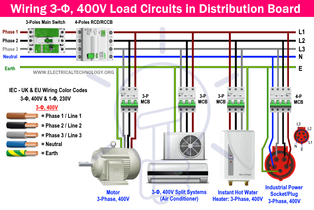
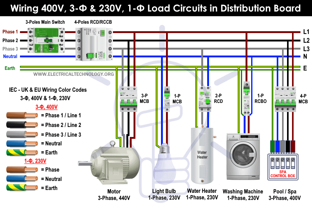
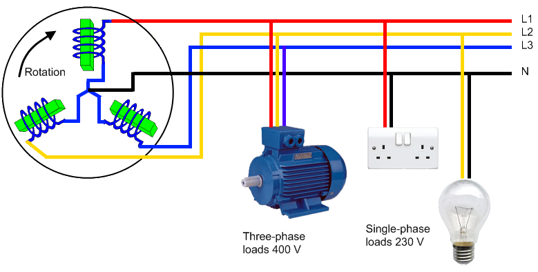 Three Phase Wiring Explained
 Three Phase Wiring Explained
