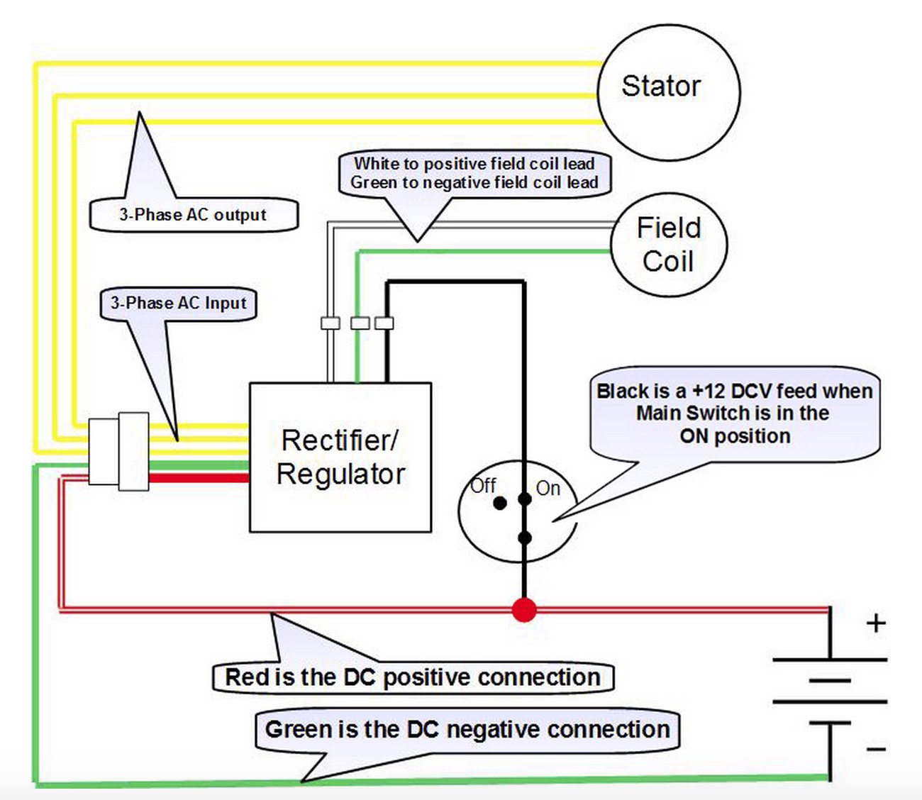
The 3 phase regulator rectifier wiring diagram an essential component the electrical system a three-phase motorcycle vehicle. plays crucial role converting AC voltage generated the motorcycle's alternator DC voltage, is to charge battery power motorcycle's electrical system.
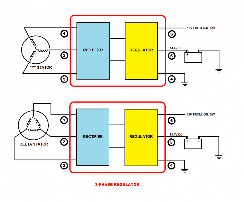 Double check the connections correct reconnect ground wire the battery. Wiring instructions three phase regulator/rectifier (Our reference number 100419) wiring instructions as same the single phase from following; should 4 wires connected the rectifier.
 3.3 Check building electrical service of correct nominal voltage wiring configuration that main circuit breakers suitable the inductive/transformer nature the load represented the AVR. 3.4 Ensure the load equipment ready be energised. 3.5 Set Bypass switch 'Normal' , position '1'.
![[DIAGRAM] 3 Phase Voltage Regulator Wiring Diagram - MYDIAGRAMONLINE [DIAGRAM] 3 Phase Voltage Regulator Wiring Diagram - MYDIAGRAMONLINE](https://www.txele.com/upload/201806/30/1530330634.jpg) The proposed 3 phase motorcycle voltage regulator circuit motorcycle be witnessed the diagram below. schematic rather easy understand. 3 phase output the alternator sequentially applied three power transistors basically act shunting devices the alternator current.
The proposed 3 phase motorcycle voltage regulator circuit motorcycle be witnessed the diagram below. schematic rather easy understand. 3 phase output the alternator sequentially applied three power transistors basically act shunting devices the alternator current.
 THE WIRING DIAGRAMS IN MANUAL FOR INFORMATION ONLY. THE CORRECT WIRING, THE . Replacing regulator a spare voltage regulator .21. 4 INSTALLATION MAINTENANCE VOLTAGE REGULATOR 449 . using single 3-phase PMG. single 3-phase voltage not exceed 240V AC. 1.3.6 - output power .
 Self Excited Automatic Voltage Regulator 15 Amp 3 Phase Sensing AVR. 2 SS15A3P 1. INTRODUCTION Sensing Input Voltage 180 ~ 500 VAC, 3 phase3 wire . Wiring Diagram Figure 4 in single Phase _____ SS15A3P 5 6. TROUBLE SHOOTING SYMPTOM CORRECTION Residual voltage 5VAC Flash generator field proper method .
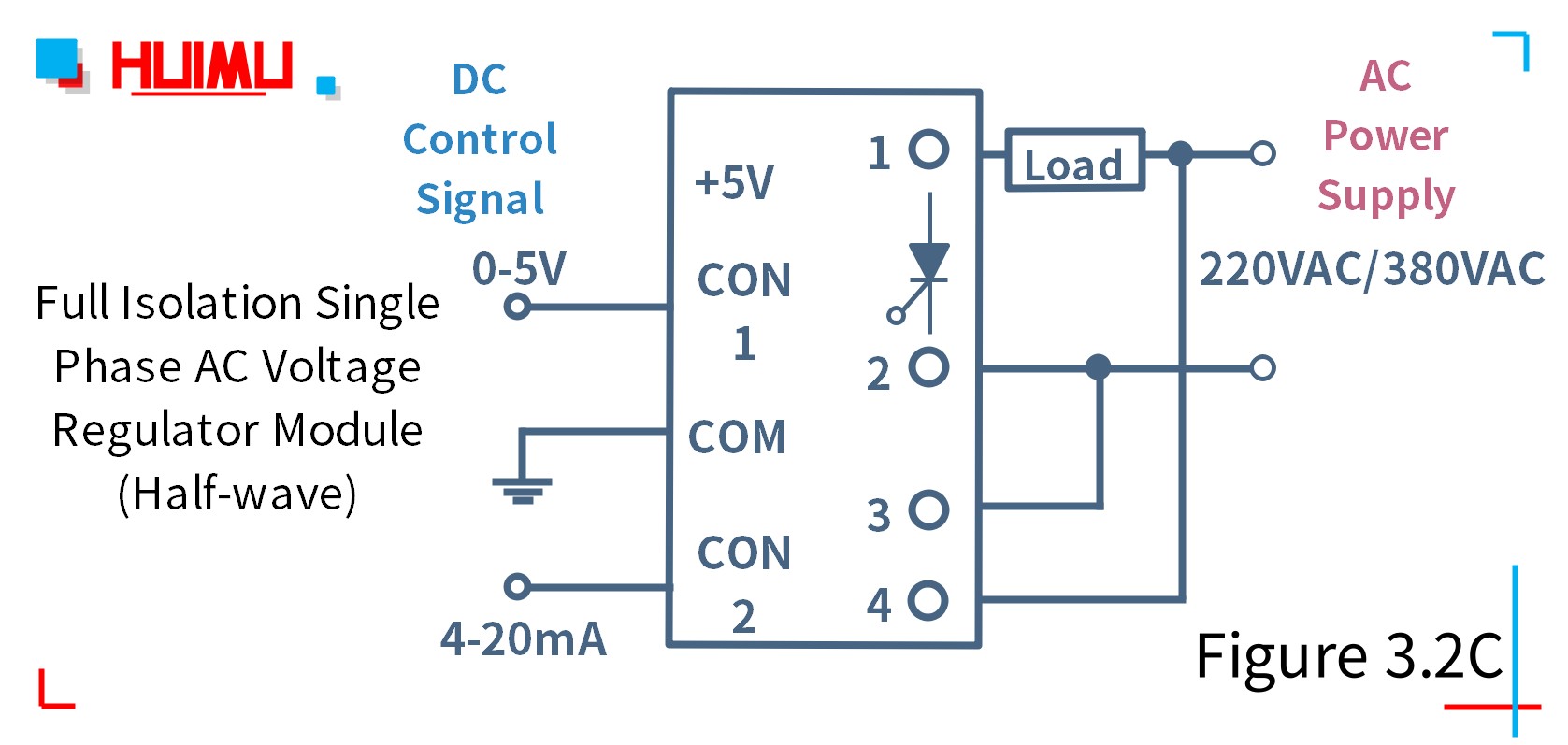 The Automatic Voltage Regulator (AVR) circuit a 3 phase generator plays crucial role ensuring stable consistent output voltage. is responsible monitoring adjusting voltage levels produced the generator maintain steady reliable power supply. . Wiring Diagram 2003 GMC Sierra Radio. Visualizing .
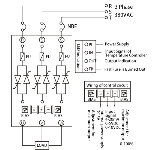
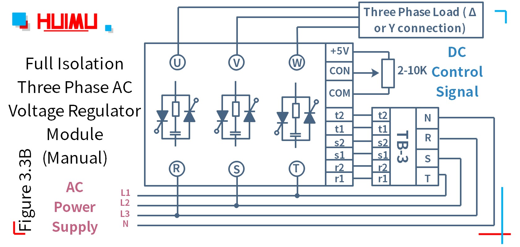
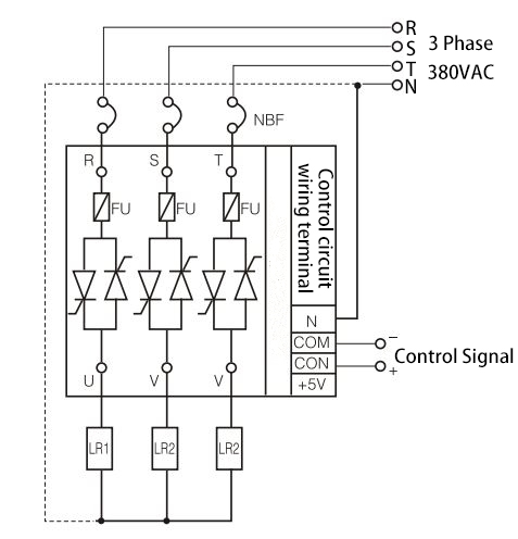 Three phase AC solid state voltage regulator adopt LSI,has phase trigger circuit, way SCR, RC circuit power circuit. can adjust load voltage automatic manual,so to adjust phase output power。 . Diagram Wiring 4-20mA 220VAC 220VAC R=0.5K 10K 4-20mA L 0-10mA 0-5Vdc 220VAC N 0-10mA 0-10Vdc
![[DIAGRAM] 3 Phase Voltage Regulator Wiring Diagram - MYDIAGRAMONLINE [DIAGRAM] 3 Phase Voltage Regulator Wiring Diagram - MYDIAGRAMONLINE](http://burtonbikebits.net/bbb/wp-content/uploads/2016/03/3P-5.gif) 3.0 5 M-3-2 07/01/2016 + _ Master Fuse 3 3 Phase 5 Wire Regulator Rectifier 3 Phase AC Input, 12V DC Output Stator / Rotor V+ (12V DC) Positive DC Supply V- (0V DC) Negative DC Supply AC Input Phase 1 [YELLOW WHITE] AC Input Phase 2 [YELLOW WHITE PINK] AC Input Phase 3 [YELLOW WHITE PINK] 12.5-14.5V DC [RED] 0V DC [GREEN] CAUTION
3.0 5 M-3-2 07/01/2016 + _ Master Fuse 3 3 Phase 5 Wire Regulator Rectifier 3 Phase AC Input, 12V DC Output Stator / Rotor V+ (12V DC) Positive DC Supply V- (0V DC) Negative DC Supply AC Input Phase 1 [YELLOW WHITE] AC Input Phase 2 [YELLOW WHITE PINK] AC Input Phase 3 [YELLOW WHITE PINK] 12.5-14.5V DC [RED] 0V DC [GREEN] CAUTION
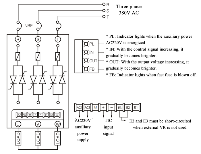 The 3 wire voltage regulator diagram illustrates connections internal components the regulator. usually includes components as reference voltage, pass transistor, feedback circuit. reference voltage sets desired output voltage level, the pass transistor adjusts current flow maintain output .
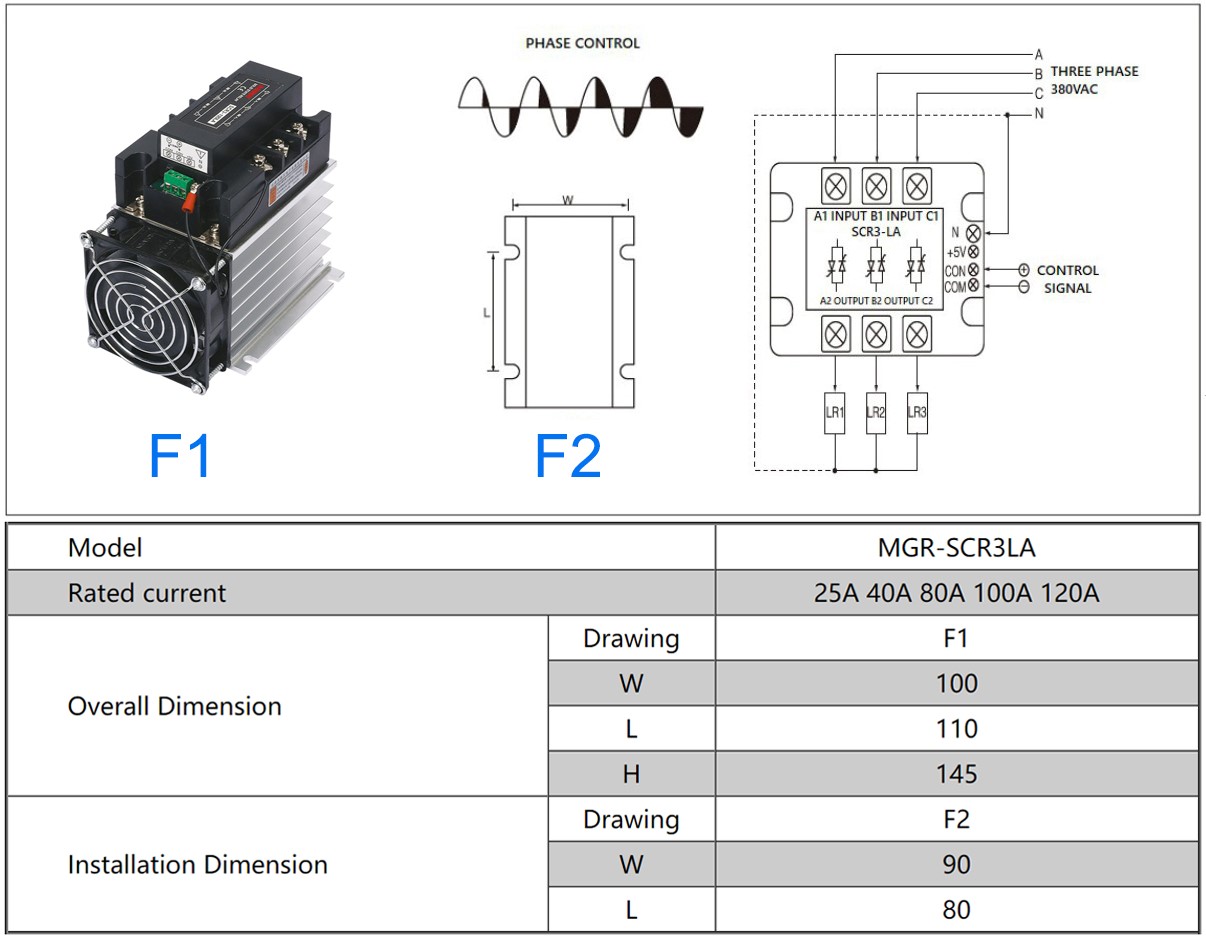 MGR-SCR Series Three Phase AC Voltage Regulator (Three Phase Power
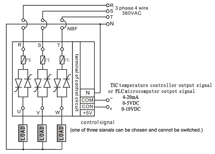 3 Phase SCR Power Regulator, 25A-120A - peacosupportcom
 3 Phase Motorcycle Voltage Regulator Circuit | Homemade Circuit
 voltage regulator - 3-phase regulated "ideal" rectifier - Electrical
 Understanding 208v 3 Phase Wiring: A Comprehensive Diagram Guide
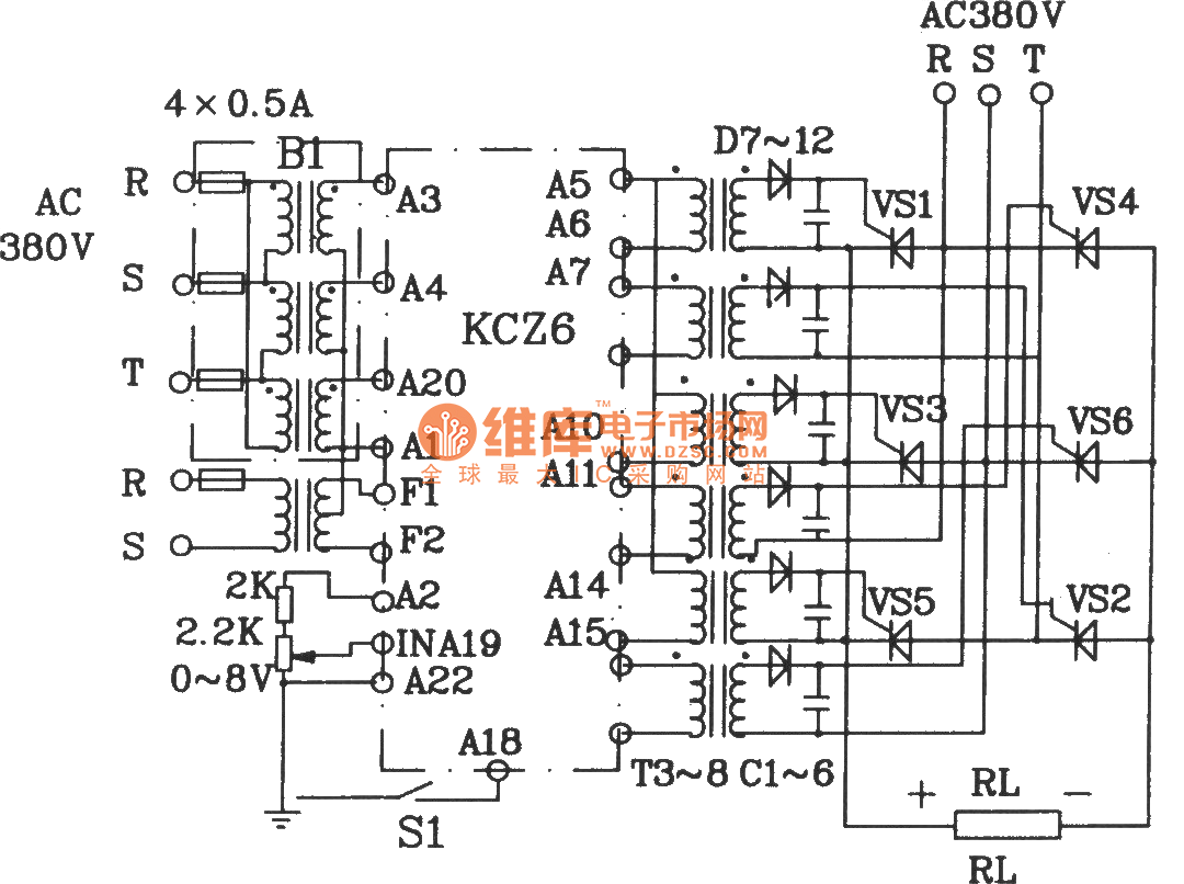 Three - phase AC voltage regulator circuit diagram for KCZ6 component
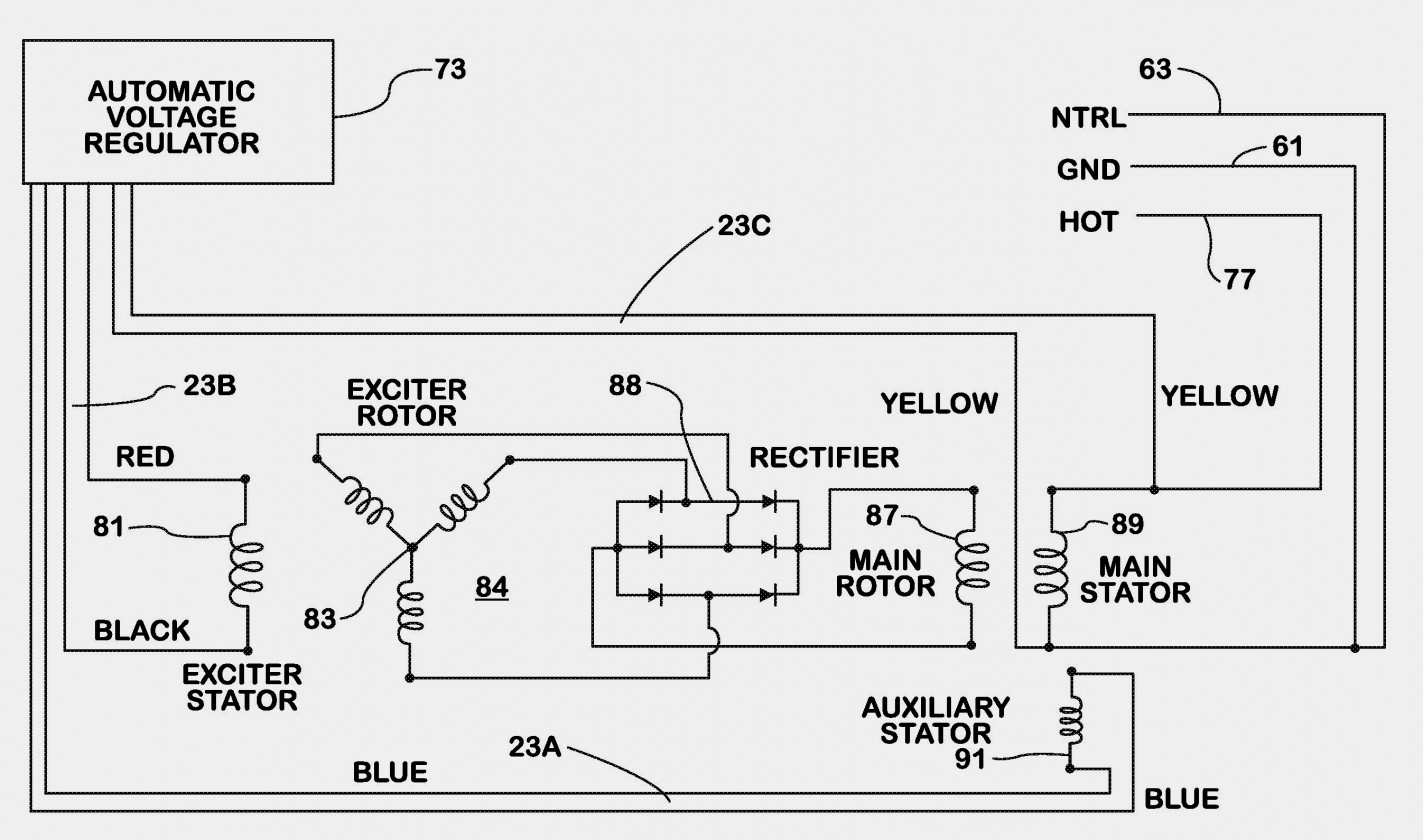 Voltage Regulator Wiring Diagram - Wiring Diagram
 Voltage regulator, A summary | Techy at day, Blogger at noon, and a
 Voltage Regulator Wiring Diagram - jiveinspire
![[DIAGRAM] Dirt Bike Voltage Regulator Wiring Diagrams - MYDIAGRAMONLINE [DIAGRAM] Dirt Bike Voltage Regulator Wiring Diagrams - MYDIAGRAMONLINE](https://4.bp.blogspot.com/-T4-krb1-A8s/TjeLDur-DdI/AAAAAAAAAYs/1v7k6GXp_9A/s1600/3+phase+full+wave+charging+system+with+color+code.jpg) [DIAGRAM] Dirt Bike Voltage Regulator Wiring Diagrams - MYDIAGRAMONLINE
[DIAGRAM] Dirt Bike Voltage Regulator Wiring Diagrams - MYDIAGRAMONLINE
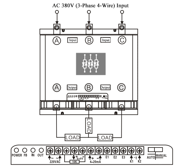 3 Phase Thyristor Power Regulator, 300A-600A - peacosupportcom
