A. WIRING DIAGRAMS A. WIRING DIAGRAMS 20 21 Typical Wiring Diagrams 3 1 2 5 36 97 1 L1 T1 T2 T3 L2 L2 3 Pump Motor Ground Level Control Ground Pressure Switch Upper Electrode Input Power (As Required Level Control) Fused Disconnect Circuit Breaker 3Ø Furnas Magnetic Starter Line Load Line Load 3 Phase Starter Magnetic .
 st4/st6 series submersible pumps• operation parts manual — rev. #1 (11/12/13) — page 27 ConTrol box wiring Diagram (Cb1456/C b1463) L1 460 VAC PHASE WIRING EXTERNAL 3-PHASE CONNECTIONS (460 VAC) POWER SOURCE CIRCUIT BREAKER RED WHITE BLACK L1 L2 L3 GREEN GROUND ON INDICATOR LAMP A2 A1 43 2 3 4 1 STOP FLOAT SWITCH START FLOAT .
 • Insure main power disconnected, turned OFF, wiring compo - nents. • Wiring be performed by qualified technicians. • Wiring Grounding be compliance national local codes. • Restrict flow a ball globe valve, 1/3 open, starting pump first time.
 Three Phase Power Supply Unbalance three phase systems true full 3-Phase Delta {3 pot system} transformer setup recommended one true 3 phase transformer. system, much than open delta 2 pot system, does guarantee good balanced power. Load unbalance still occur this

 PENTEK XE-Series 60 Hz., Single Phase, 3 Wire Induction Run Submersible Pump Motors XE-Series Motor SMC Submersible Motor Control Type Model No. (3-W) HP Volts/Hz/Ph CSIR CSCR P43B0005A1 1/2 115/60/1 SMC-IR0511 - P43B0005A2 1/2 230/60/1 SMC-IR0521 SMC-CR0521 P43B0007A2 3/4 230/60/1 SMC-IR0721 SMC-CR0721 P43B0010A2 1 230/60/1 SMC-IR1021 SMC-CR1021

 Electric Submersible Pumps . Single Phase . 115V & 230V . Phase . 208V, 230V, 460V & 575V . CAST IRON SINGLE PHASE PHASE SV400 SV750 SV750C SV1500C SV08 SV08C SV15C SV22C SV37C SV55C SV75C Read manual carefully installing, operating servicing pump models. Observe safety information.
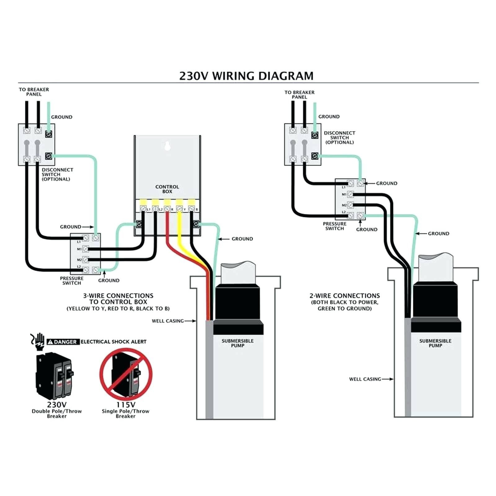 Single Phase, 3 Wire Submersible Pump Motors TABLE II: Recommended Fusing Data - 60 Hz., Single Phase 2 Wire Submersible Pump Motors INSTALLATION WIRING DIAGRAMS - SINGLE PHASE, 3 WIRE motors 11⁄ 2 HP above, magnetic starter avoid damage pressure switch. Consult factory wiring information. Page 4 2 Wire Hookup.
 "SP/ST" series 4 Submersible Pump Installation Operation Manual. electrical connections be performed qualified personnel working accordance National Local Electrical Codes. Wiring Pump - Single Phase. a. wire installation FRANKLIN 0.75kW motor 1.5kW PSC motor. 1.
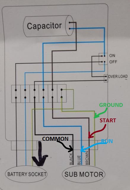
 3 Wire Submersible Pump Wiring Diagram
 3 Phase Submersible Pump Wiring Diagram Pdf
 3 phase Submersible pump starter connection | Part 1 - YouTube
 Three Phase submersible pump with float switch | Engineers CommonRoom
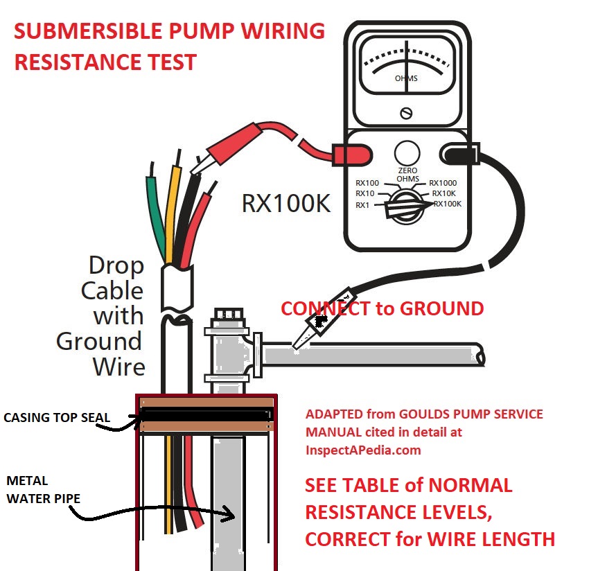 Submersible Well Pump Wire And Connectors
 3 Wire Submersible Well Pump Wiring Diagram - Printable Form, Templates

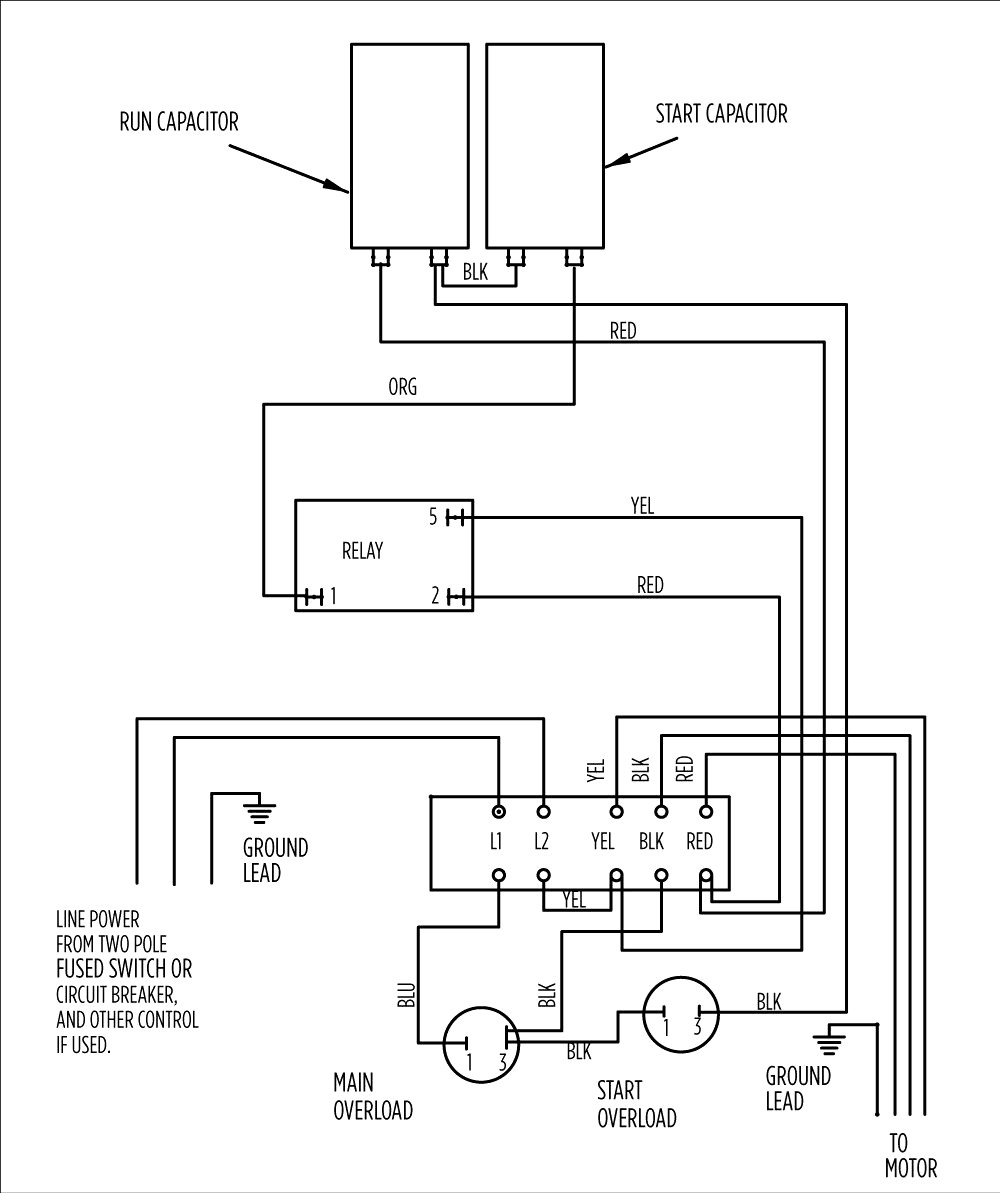 3 Wire Submersible Well Pump Wiring Diagram - Wiring Diagram
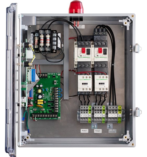 3 phase submersible pump wiring diagram pdf - Wiring Diagram and Schematics
 3 Phase Submersible Pump Wiring Diagram Pdf
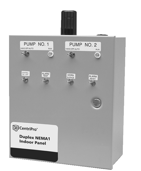 3 Phase Submersible Pump Wiring Diagram Pdf Submersible Pump Diagram 3