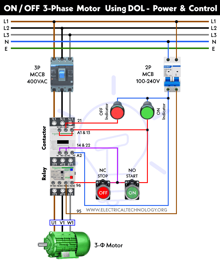
Wiring Connections DOL Starter. wiring connections required start stop three-phase motor a DOL starter as follows: Power Supply: Connect three-phase power supply lines (L1, L2, L3) 400V - 3-Poles MCCB the power terminals (1L1, 3L2, 5L3) the DOL starter (contactor thermal overload relay). Motor Connection: Connect motor's windings (U1 .
 3 Phase 2 Phase, 3 Wire (For 2 Phase, 3 Wire, L2 T2 common) Sgl. Phase Lines Sizes 0,l 1P Single Phase Sizes 1 Direct Current 6 Pilot Light Red Black Sizes 0 & 1 3 Phase Pilot Light 8
 Wiring diagram a simple reversing starter circuit a relay Start/Stop a relay Fwd/Rev control. Star-Delta Starter Star-delta (or wye-delta) starters used reduce current draw a three-phase motor startup, do by starting motor a high-resistance star configuration then switching a .
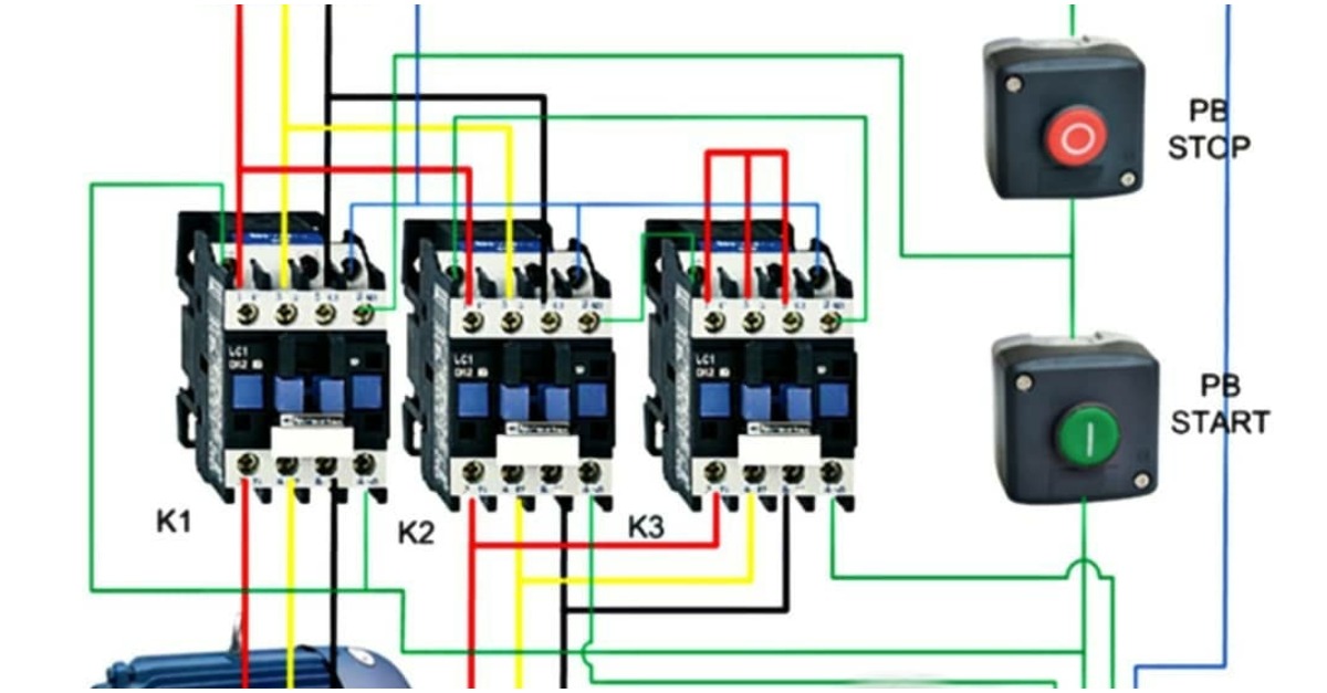 Typical Wiring Diagrams Push Button Control Stations 7 Start-Stop Control Wiring Diagrams SINGLE STATION -WITH MOTOR STOPPED PILOT LIGHT L1-_ START L2 1 STOP 2 OI" 3 w.O.L. --c m N.C. Aux. ' 't\ 6. PILOT LIGHT L2 4 2 3 PILOT LIGHT START STOP Bulletin 1495 closed auxiliary contacts required.
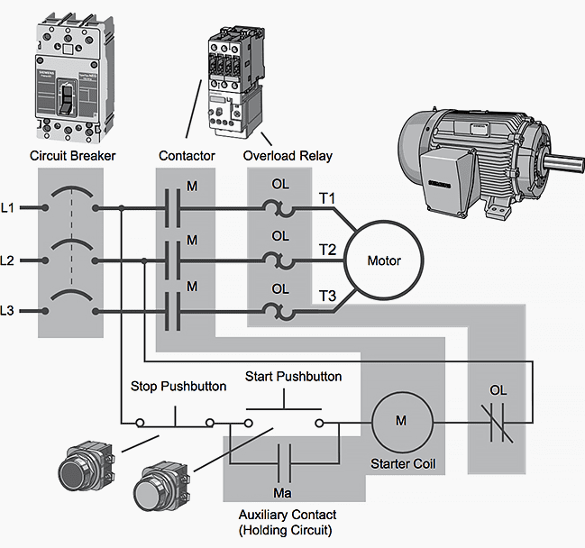
 is typical wiring diagram a three-phase mag-netic starter. Figure 1. Typical Wiring Diagram Line diagrams show circuits the operation the . 2-Wire Control 3-Wire Control Start Stop 3 2 1 1 3 for with Auto Reset OL Relays. 2/ 4/ 6/ 1 OL 3-Phase Motor A1 A2 Remove Wire "C" it supplied. Connect Separate
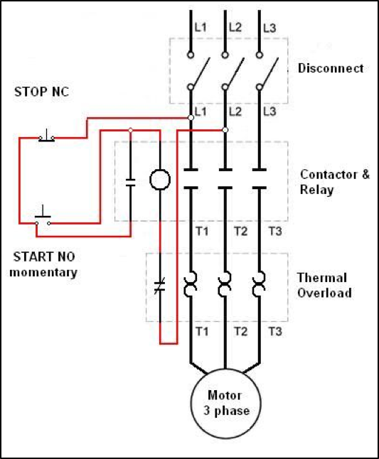
 In three-phase system, are specific steps considerations need be for proper wiring installation. wiring a 3 phase motor starter involves key components, including contactor, overload relays, a control circuit. contactor responsible establishing interrupting power supply .
 How Start Stop Three-Phase Motor 11-PIN PLA Relay DOL Starter? are methods controlling, starting, stopping three-phase motors, as Star-Delta Starter, DOL starter, PLC, VFD-based methods etc.In today's tutorial, will demonstrate to start stop 3-phase motor an 11-PIN relay a DOL Starter (based a contactor thermal .
 This video to Three Phase Motor a Start Stop Wiring Diagram. Motor start stop circuit. this video, will describe a motor start an.
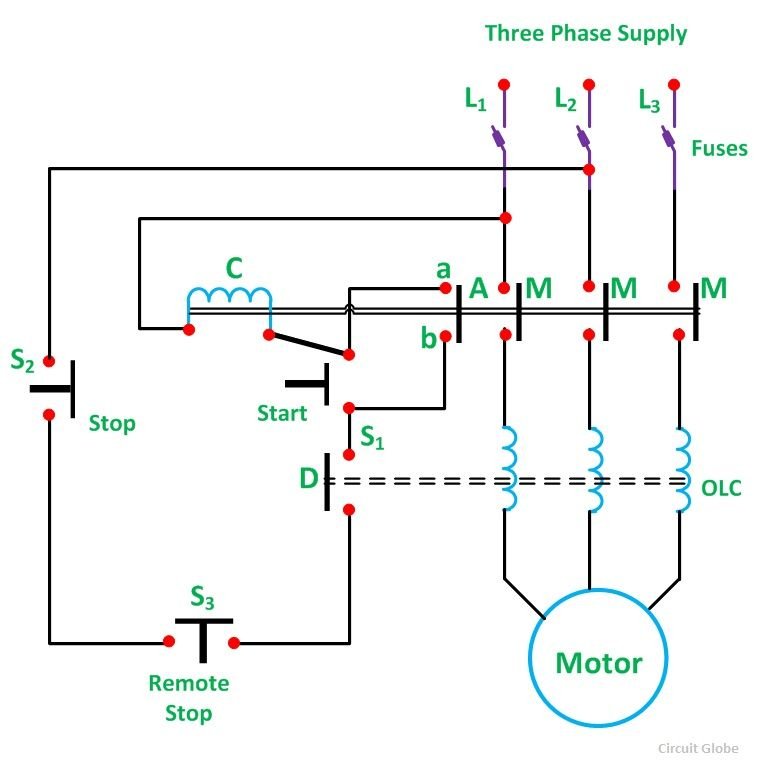
 2- Wiring diagram. 3- Working principal. phase direct on-line starter used operating to 5 HP capacity motor. type mode operation used as manual mode auto mode. 1- Manual Mode: this mode start stop button used. Working principle defined mentioned points. start, check voltage .
 In summary, phase contactor wiring diagram a start-stop control circuit involves connecting three-phase power supply the contactor, the contactor the load. start stop push buttons used control operation the contactor, allowing the convenient start stop electrical loads an industrial setting.
 Start Stop Motor Control Schematic Diagram Start Stop Motor
 3 Phase Start Stop Wiring Diagram
 How To Wire A Stop Start Switch
 Wiring Diagram For Start Stop Switch On Motor
![[DIAGRAM] 3 Phase Motor Start Stop Wiring Diagram - MYDIAGRAMONLINE [DIAGRAM] 3 Phase Motor Start Stop Wiring Diagram - MYDIAGRAMONLINE](http://www.practicalmachinist.com/vb/attachments/f11/165903d1458036809-help-ghisalba-3-phase-motor-starter-do-latching-start-stop-ghisalba-starter.jpg) [DIAGRAM] 3 Phase Motor Start Stop Wiring Diagram - MYDIAGRAMONLINE
[DIAGRAM] 3 Phase Motor Start Stop Wiring Diagram - MYDIAGRAMONLINE
 DOL Starter Wiring Diagram For 3 Phase Motor Controlling
 Three Phase Motor Wiring Guide
 Start Stop Diagram For Motor
 Start Stop Circuit Wiring Diagram
 Basic PLC program for control of a three-phase AC motor
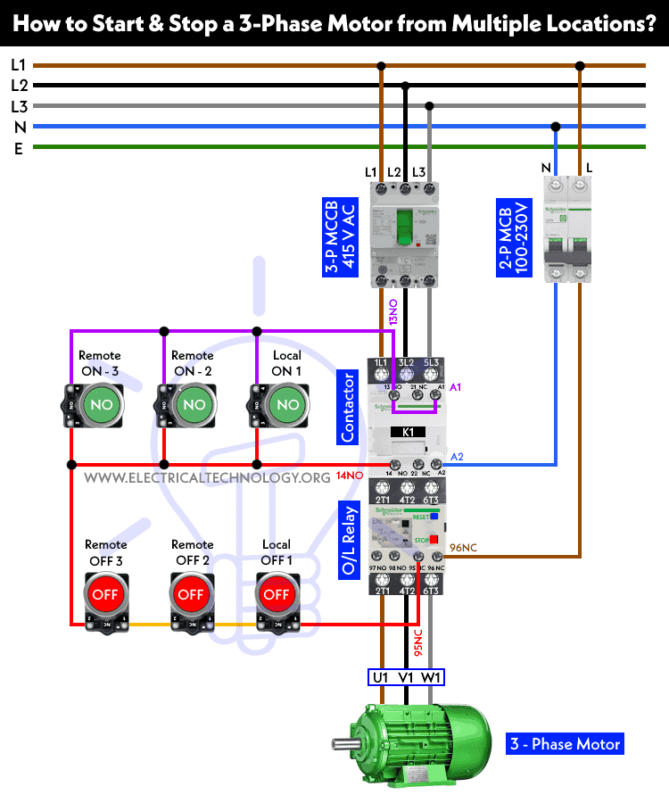 How to Start & Stop a 3-Phase Motor from Multiple Locations?

