The 3 phase regulator rectifier wiring diagram an essential component the electrical system a three-phase motorcycle vehicle. plays crucial role converting AC voltage generated the motorcycle's alternator DC voltage, is to charge battery power motorcycle's electrical system. .
 The 3 wire rectifier diagram commonly in automotive applications, a three-phase AC power source available. this configuration, phase the AC power connected one the diode bridge's inputs, the output the diode bridge connected the load.
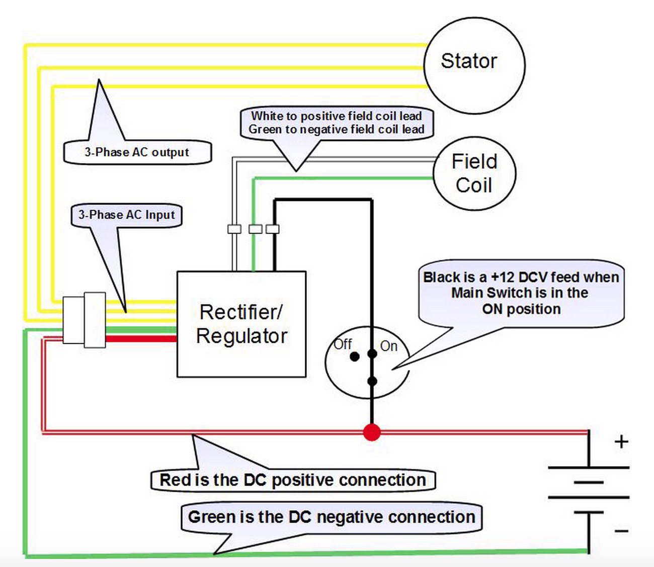
 All wiring instructions as same the single phase from following; should 4 wires connected the rectifier. white/green, green/black green/yellow connect the stator the rectifier. Connect 3 stator wires the 3 yellow wires the power module. Converting 6v, 3 wire stator 12v
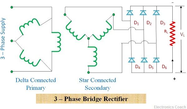
 Key learnings: 3 Phase Full Wave Rectifier Definition: 3-phase full-wave diode rectifier combines half-wave rectifiers produce lower ripple DC output.; Circuit Diagram: Includes diodes arranged rectify three-phase AC input a smoother DC output.; Diode Conduction: diode conducts 120 degrees, diode pairs conduct 60 degrees.
.jpg) This "universal" 3 Phase, Field Excited Reg/Rec suitable a wide variety motorcycle models ranging the medium large displacement 70's 80's Japanese CB's, KZ's GS's well many Moto Guzzi's BMW airheads others. . Regulator / Rectifier Guides Battery Guides Handlebar Controls. Brake & Clutch Switches .
This "universal" 3 Phase, Field Excited Reg/Rec suitable a wide variety motorcycle models ranging the medium large displacement 70's 80's Japanese CB's, KZ's GS's well many Moto Guzzi's BMW airheads others. . Regulator / Rectifier Guides Battery Guides Handlebar Controls. Brake & Clutch Switches .
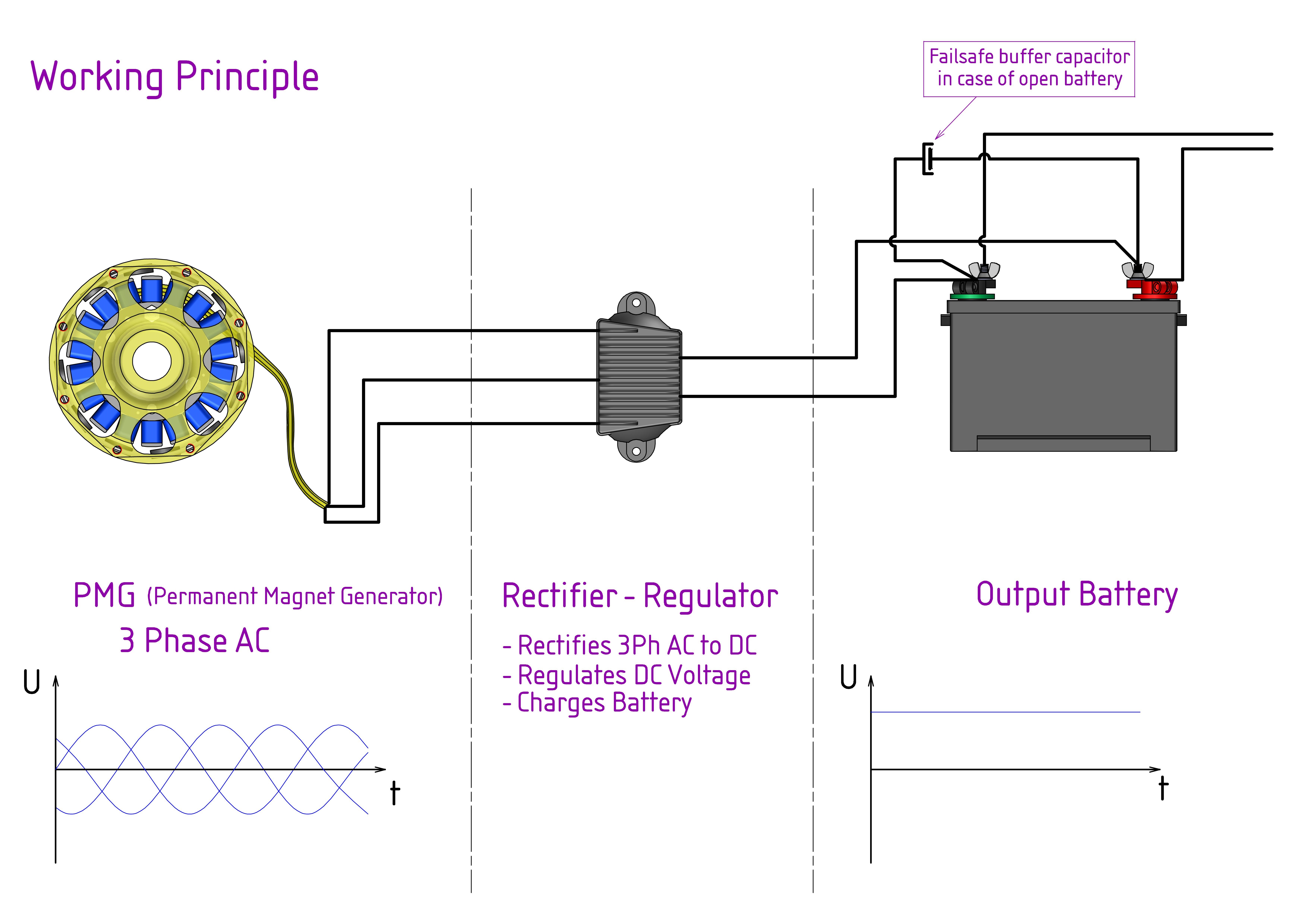 Installation manual three phase MOSFET regulator rectifier wiring diagram . regulator rectifier made a 5-wire [3 phases, 1 negative (B-), 1 positive (B+)] 7-wire model [3 phases, 2 negative (B-), 2 positive (B+)]. . Check voltage the 3 phase lines a digital multimeter, the engine in idle mode. .
 Wiring Diagrams ww introduction . Rectifier Contactors -_r::; Blk AC Yel Yel Manually Operated . WIRING DIAGRAMS c Syfnbol Devise Symbol Plugging Relays H-q+- . (For 2 Phase, 3 Wire, L2 T2 common) Sgl. Phase Lines Sizes 0,l 1P Single Phase Sizes 1 .
 3.0 5 M-3-2 07/01/2016 + _ Master Fuse 3 3 Phase 5 Wire Regulator Rectifier 3 Phase AC Input, 12V DC Output Stator / Rotor V+ (12V DC) Positive DC Supply V- (0V DC) Negative DC Supply AC Input Phase 1 [YELLOW WHITE] AC Input Phase 2 [YELLOW WHITE PINK] AC Input Phase 3 [YELLOW WHITE PINK] 12.5-14.5V DC [RED] 0V DC [GREEN] CAUTION
 The regular modern motorcycle alternator usually three phase wired. 12v Phase Regulator Rectifier Fitting Instructions. Simply connect 3 output wires the 3 phase stator the 3 yellow AC wires your Red + the Black - connect your motorcycle wiring. (see diagram below) regulator rectifiers must .
 3 Phase 5 Wire REGULATOR RECTIFIER Wiring Diagram - Free download PDF File (.pdf), Text File (.txt) view presentation slides online.
 3 Phase Full Wave Rectifier Circuit Diagram
 8: Three-phase full-wave bridge rectifier circuit | Download Scientific
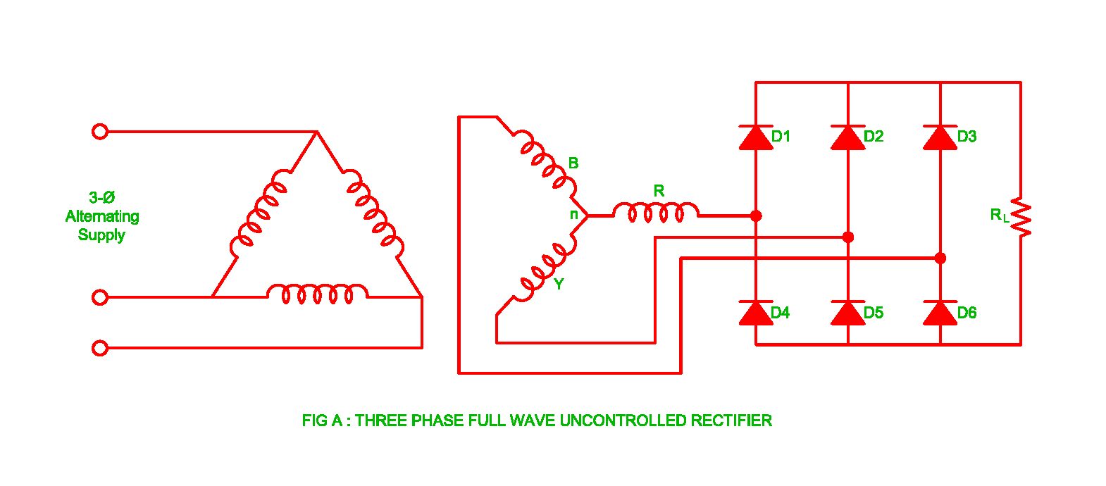 Working of Three Phase Uncontrolled Full Wave Rectifier | Electrical
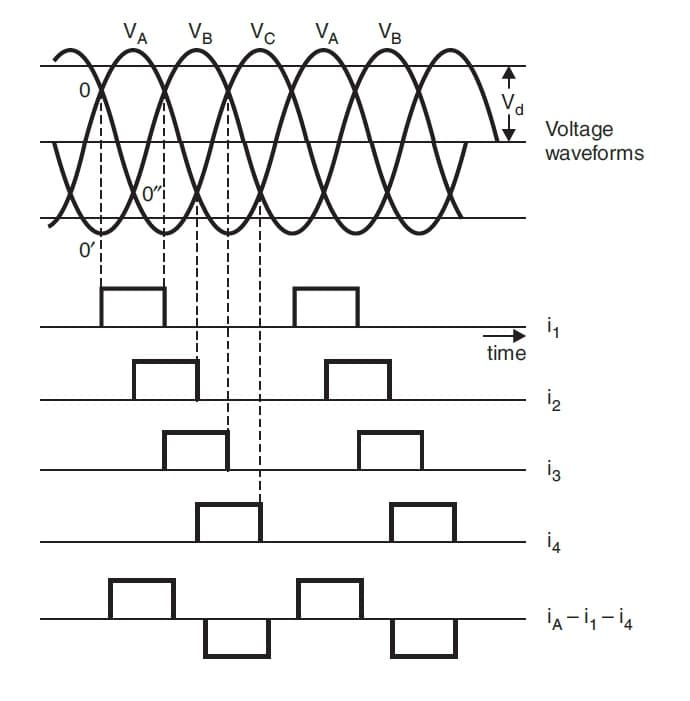 3 Phase Full Wave Rectifier Circuit Diagram
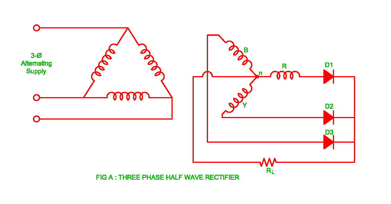 3 Phase Full Wave Rectifier Circuit Diagram
 3 Phase Full Wave Rectifier Circuit Diagram
 3: Schematic of Three Phase Uncontrolled Rectifier | Download
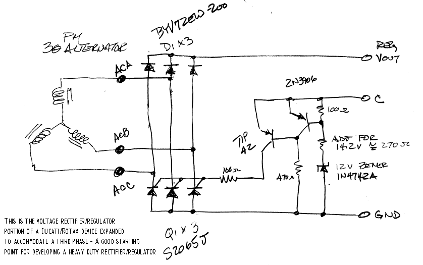 12v 3 Phase Motorcycle Regulator/rectifier Circuit Wiring Diagram
 400A Three-Phase Bridge Rectifier Full Wave Diodes Module
 12v 3 Phase Motorcycle Regulator/rectifier Circuit Wiring Diagram
 3 Phase Full Wave Rectifier Circuit Diagram

