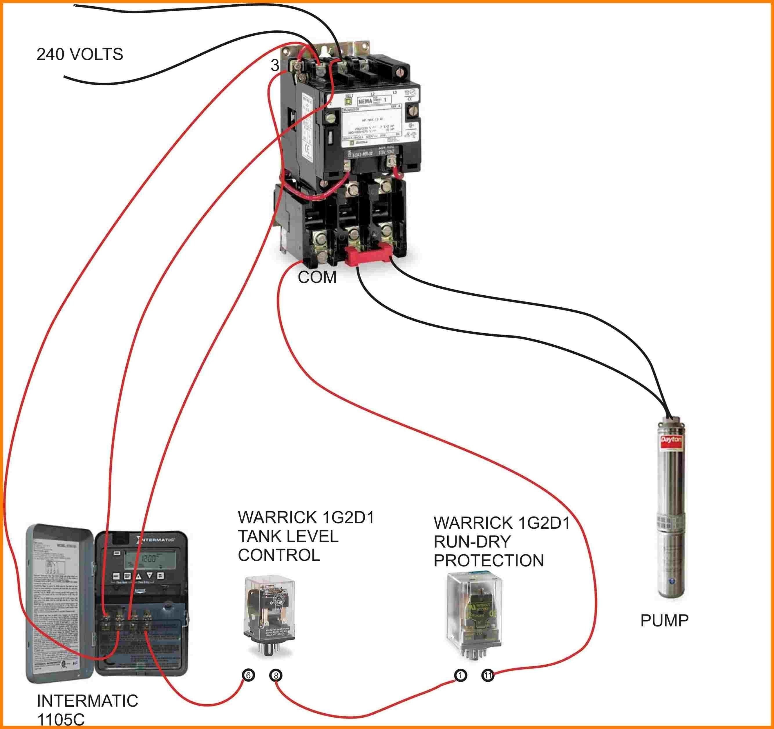
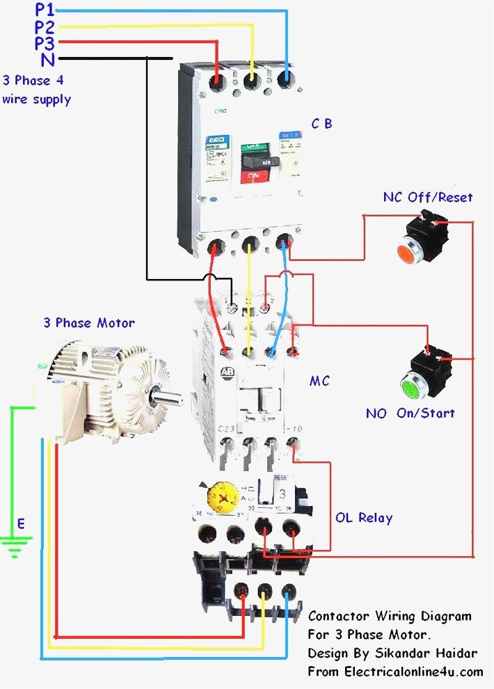
The wiring diagram a magnetic contactor three-phase systems typically includes components, as power supply lines, control circuit, thermal overload relay, motor. power supply lines deliver three-phase AC voltage the contactor, the control circuit consists the start stop buttons switches.
 Wiring Diagrams ww introduction booklet been prepared a guide some the ways Allen-Bradley's manual magnetic across-the-line starters be applied. will serve a . 3 Wire (For 2 Phase, 3 Wire, L2 T2 common) Sgl. Phase Lines Sizes 0,l 1P Single Phase .
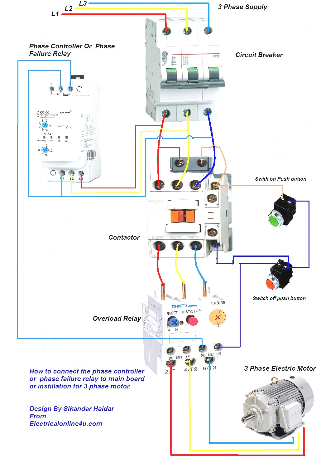 A 3 phase contactor an electrical device to control switch three-phase motors other three-phase loads. is essential component industrial commercial electrical systems, ensuring efficient safe operation machinery equipment. wiring a 3 phase contactor involves connecting to power supply the .
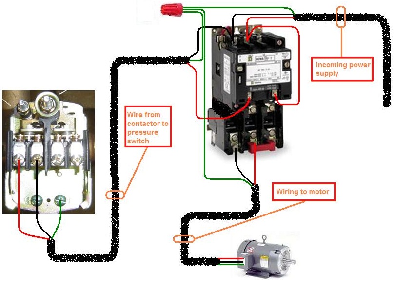
 Wiring diagrams, called "main" "construc-tion" diagrams, show actual connection points the wires the components terminals the controller. show relative location the components. can used a guide wiring controller. Figure 1 a typical wiring diagram a three-phase mag-

 The wiring diagram a 3-phase motor contactor typically includes components, as power supply lines, control circuit lines, auxiliary contacts. . Magnetic contactors an electromagnet control opening closing the contacts. Air contactors, the hand, air pressure operate contacts. .
 A single-phase induction motor not work a 3 phase be done. 3 phase motor, use electrical devices starting, off, resetting, magnetic contactor one them that's today disuse contactor wiring a complete explanation. 3 power systems, use devices the induction motor .

 The wiring diagram a 3 phase contactor reveals arrangement the wires terminals are to connect contactor the power source the load. also shows use overload relays thermal protection devices, are essential preventing damage the equipment case any faults.
 The step wiring magnetic contactor a three-phase motor to identify three power lines will connected. are typically labeled L1, L2, L3 the contactor. contactor then wired that power each these lines be switched and independently.
 How To Wire A 3 Phase Contactor
 How to Wire a Three Phase Magnetic Contactor: A Complete Diagram

 3 Phase Magnetic Contactor Wiring Diagram
 How To Wire A 3 Phase Contactor
 How To Wire A 3 Phase Contactor
 How to Connection Contactor Holding Circuit | 3-Phase Magnetic
 How to wire Contactor, Over Load Relay(OLR) with 3 phase Motor control
 A Simplified 3 Phase Contactor Diagram for Beginners
 How to Wire a Three Phase Magnetic Contactor: A Complete Diagram
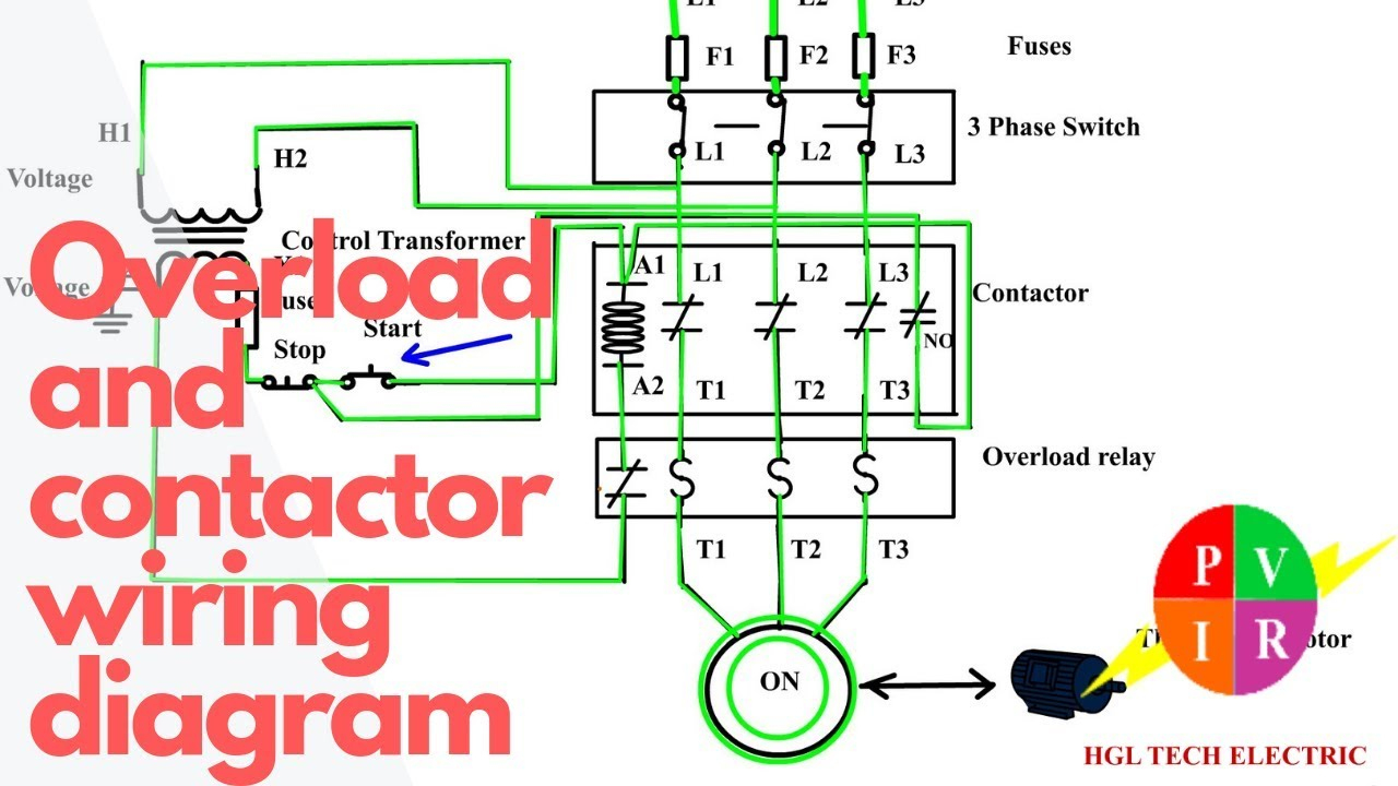 3 Phase Contactor Wiring Diagram Start Stop - Cadician's Blog
