Wiring Diagrams ww introduction . Contactors -_r::; Blk AC Yel Yel Manually Operated . WIRING DIAGRAMS c Syfnbol Devise Symbol Plugging Relays H-q+- (P4Of.t Shown) . (For 2 Phase, 3 Wire, L2 T2 common) Sgl. Phase Lines Sizes 0,l 1P Single Phase .
 3 3 position selector switch wire contact device hand auto 1 l.h. coil term.(a1) or momentary contact pushbutton stations start stop start-stop pushbutton start stop 1 2 3 2 pos selector switch off start 1 stop 1 2 3 l.h. coil term. (a1) (remove wire "a") l.h. coil term. (a1) l1 l2 l3 m motor t1 t2 t3 v 4 4 m .
 single-phase wiring diagrams use wiring diagram supplied motor nameplate. w2 cj2 ui vi wi w2 cj2 ui vi wi cow voltage high voltage t4 til t12 10 til t4 t5 ali l2 t12 ti-blu t2-wht t3.org t4-yel t5-blk t6-gry t7-pnk t8-red t9-brk red tio-curry tii-grn t12-vlt t4 til t12
 Wiring diagrams, called "main" "construc-tion" diagrams, show actual connection points the wires the components terminals the controller. show relative location the components. can used a guide wiring controller. Figure 1 a typical wiring diagram a three-phase mag-

 Single Three Phase Wiring Diagrams NOTES: 1. Symbols electrical representation only. 2. Compressor fan motor furnished inherent thermal protection. . not the contactor be energized the phasing not correct. phasing reversed, . Fig. 3 - Wiring Diagram — Model size 3 -- 5 tons, 575/3 .
 A single-phase induction motor not work a 3 phase be done. 3 phase motor, use electrical devices starting, off, resetting, magnetic contactor one them that's today disuse contactor wiring a complete explanation. 3 power systems, use devices the induction motor .
 The wiring diagram a 3-phase motor contactor typically includes components, as power supply lines, control circuit lines, auxiliary contacts. components work to control flow electricity the motor protect from potential damage. the wiring diagram carefully help connect .
 3-Phase Contactor Wiring Diagrams⁚ Comprehensive Guide. guide comprehensive information 3-phase contactor wiring diagrams‚ including DOL starters‚ reversing starters‚ multiple start/stop locations. PDF resources further learning materials also included enhanced understanding practical application.
 Step-by-step guide wiring three phase contactor. Wiring three phase contactor a crucial step setting an electrical system. contactor an electrical switch controls flow electricity a phase circuit. guide provide with step-by-step process help wire three phase contactor correctly.
 Schematic And Wiring Diagram Of 3 Phase Contactor - Wiring Pedia
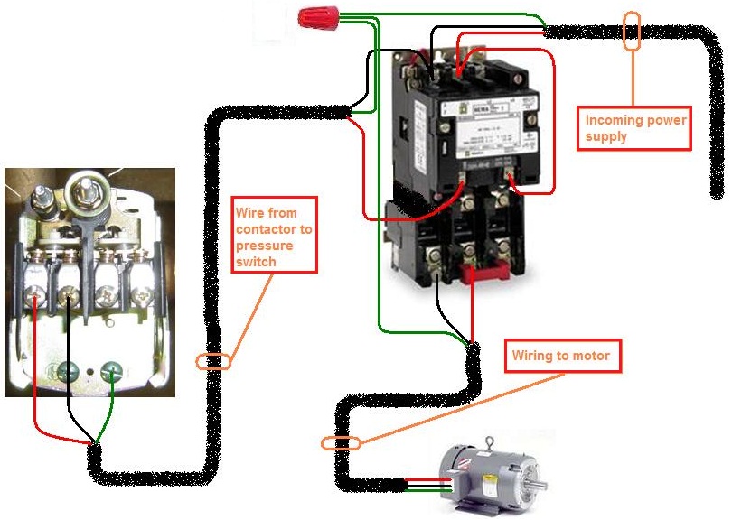 How To Wire A 3 Phase Contactor
 3 Phase Contactor Wiring Diagram With Timer
 3 phase contactor with overload wiring diagram pdf 3 phase contactor
 3 Phase Contactor with Overload Wiring Diagram PDF: Get Started with
 3 Phase Contactor Wiring Single Phase
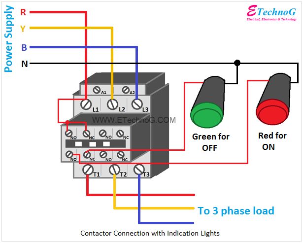 Contactor Wiring Diagram A1 A2

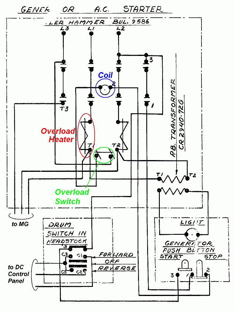 3 Phase Contactor Wiring Diagram Start Stop Pdf For Your Needs
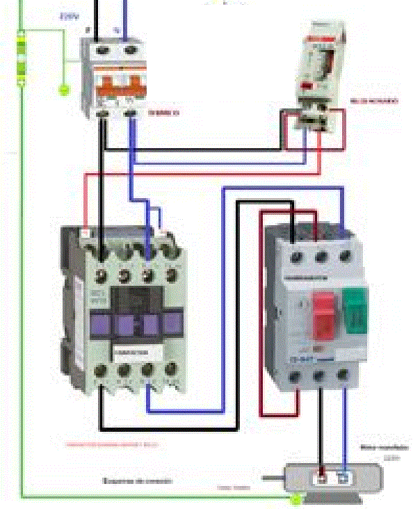 How To Connect 3 Phase Contactor
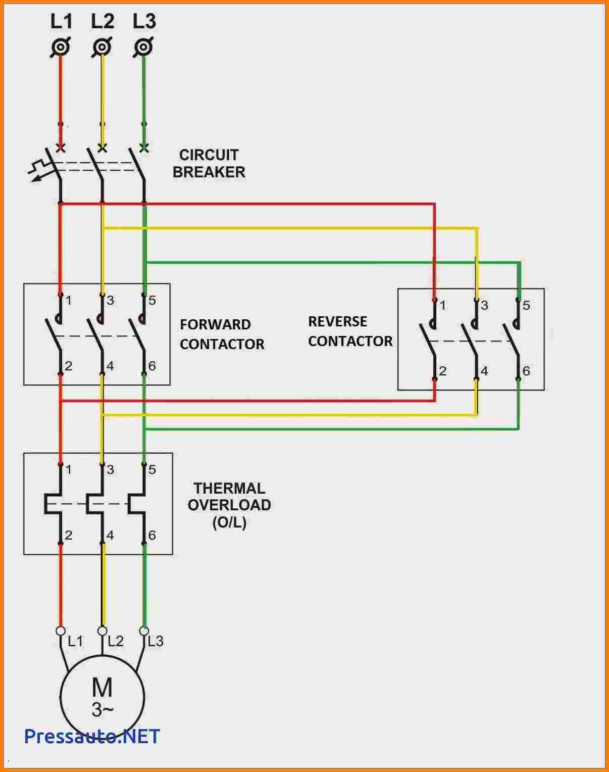 Three Phase Contactor Wiring Diagram Collection