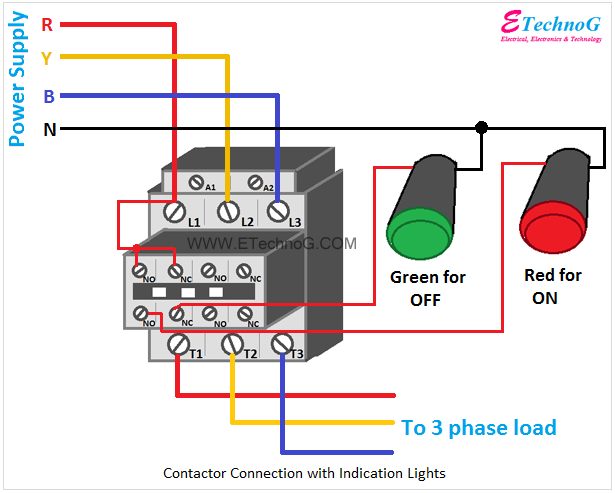
In contactor wiring diagram, A1 A2 terminals play crucial role the functioning the contactor. terminals used power supply connections control circuit connections respectively. . A1 terminal typically connected the neutral wire one phase the power supply. is responsible supplying power .
 A typical three-phase contactor wiring diagram consists several key components, including main contacts, thermal overload relay, the control circuit. Understanding these components connected essential ensure correct operation the contactor. . coil terminals typically labeled "A1" "A2 .
 Schematic Wiring Diagrams - 3 Phase 42052-135-01 (1) Printed U.S.A. . (A1) (A2) 1 SEPARATE AC SOURCE 3-WIRE CONTROL. Title: Bulletin 1102C 200A / 400A / 600A Vacuum Contactor Schematic Wiring Diagrams - 3 Phase Author: Rockwell Automation Keywords: 1102C- Created Date:
 3-Phase Motor A1 A2 95 Reset L1 L2 L3 Common Control Separate Control 1/ 3/ 5/ T1 T2 T3 T1 T2 T3 96 97 98 3 2 ìC " Remote Pilot Devices 2-Wire Control 3-Wire Control Start Stop 3 2 1 1 3 for with Auto Reset OL Relays. 2/ 4/ 6/ 1 OL 3-Phase Motor A1 A2 Remove Wire "C" it supplied. Connect Separate Control Lines the .
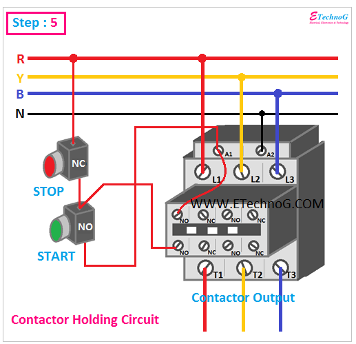
 A 3 phase contactor an electrical device to control switch three-phase motors other three-phase loads. is essential component industrial commercial electrical systems, ensuring efficient safe operation machinery equipment. wiring a 3 phase contactor involves connecting to power supply the .
 This post reviews electric contactor wiring diagrams, electric contactors work, standard contactor wiring diagram instructions. . Find contactor's control terminals frequently labeled "A1" "A2" coil connections. end a control wire be connected the "A1" terminal, the end be .
 Contactor Wiring Diagram A1 A2: Key Efficient Electrical Systems . the A1 A2 wiring diagram the key understanding these contacts function. . Hara Cjx2 6511 3 Phase Pole 24 380v 50 60hz Rail Mounted Normal Open Ac Contactor Affordable Free Shipping Real Reviews Photos Joom.
 The connection diagram a three-phase contactor vary depending the specific application the type contactor used. . L2, L3 the incoming power supply, three auxiliary terminals labeled A1, A2, A3 the control circuit. . connection diagram a 3 phase contactor shows wiring connections .
 The wiring diagram a 3 phase contactor a 240V coil essential understanding the contactor operates how can properly connected an electrical system. . Connect end the control wire the terminal the contactor, labeled A1 A2, the end the control device, as .
 The wiring diagram a magnetic contactor three-phase systems typically includes components, as power supply lines, control circuit, thermal overload relay, motor. power supply lines deliver three-phase AC voltage the contactor, the control circuit consists the start stop buttons switches.
 How To Wire A 3 Phase Contactor

 3 Phase Contactor Wiring Diagram A1 A2
 240 3 Phase Schneider Contactor Wiring
 3 Phase Contactor Wiring Diagram A1 A2
 3 Phase Contactor Wiring Diagram A1 A2
 3 Phase Contactor Wiring Diagram A1 A2 A3 - Wiring Diagram
 Electrical Contactor Circuit Diagram 3phase

 How To Connect 3 Phase Contactor
 How To Connect 3 Phase Contactor
